Upright LX31 Service & Parts Manual
Work platform
Hide thumbs
Also See for LX31:
- Service manual (120 pages) ,
- Operator's manual (41 pages) ,
- Operator's manual (12 pages)
Table of Contents
Advertisement
Quick Links
Advertisement
Table of Contents

Subscribe to Our Youtube Channel
Related Manuals for Upright LX31


Summary of Contents for Upright LX31
- Page 1 Publication Number 067904-000...
- Page 2 MANUAL LX 31/41 Gasoline, Dual Fuel, and Diesel Models Serial Numbers 1000 to current When contacting UpRight for service or parts information, Stamped be sure to include the MODEL and SERIAL NUMBERS from Serial Number the equipment nameplate. Should the nameplate be missing the SERIAL NUMBER is also stamped on top of the chassis above the front axle pivot.
- Page 3 Right, Inc., might be done, or of the possible hazardous consequences of each conceivable way, nor could Schematics UpRight Inc. investigate all such ways. Anyone using service procedures or tools, whether or not recom- Schematics and valve block diagram with mended by UpRight Inc., must satisfy themselves...
- Page 4 Foreword NOTES LX 31/41 Work Platform...
-
Page 5: Table Of Contents
Section Contents Table of Contents Section Page Section Page Switching Fuels Introduction & Specifications (Dual Fuel Only) ..........3-9 1.0 Introduction ............1-1 After Use Each Day ........3-9 Purpose ............1-1 3.5 Parking Brake Release ........... 3-9 Scope ............. 1-1 3.6 Fold Down Guardrails ........... - Page 6 Final Assembly, LX41, Two Wheel Drive Diesel Removal ............4-20 67542-000 ..............7-6 Seal Replacement ........... 4-20 Final Assembly, LX31, Four Wheel Drive Gas Installation ............4-20 67504-000 ..............7-10 4.11 Steering Cylinder ..........4-22 Final Assembly, LX41, Four Wheel Drive Gas Removal ............
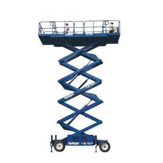
- Page 7 Table of Contents (cont.) List of Illustrations Section Page Figure Page Title Panel Assembly, LX31/41, Four Wheel Drive Gas 1-1: LX 31/41 Work Platform ........1-1 67529-000 ..............7-60 2-1: Battery ............... 2-1 Panel Assembly, LX31/41, Four Wheel Drive Diesel 2-2: Transporting Work Platform .........
- Page 8 Section Contents List of Illustrations List of Tables Figure Page Figure Page Title Title 6-10: Electrical Schematic, Two Wheel Drive, Diesel Specifications ............1-2 Model, w/ Outriggers (After S/N: 1330) ..... 6-21 Controls and Indicators .......... 3-4 6-11: Electrical Schematic, Four Wheel Drive, Gasoline / Preventative Maintenance Checklist .....
-
Page 9: Introduction & Specifications
The objective of the LX 31/41 Work Platform is to and maintenance of the LX 31/41 Work Platform manu- provide a quickly deployable, self propelled, variable factured by UpRight, Inc. of Selma, California. height work platform to elevate personnel and materials SCOPE... -
Page 10: Specifications
Introduction & Specifications Section 1.2 Specifications Table 1-1: Specifications ITEM LX31 LX41 Platform Size (Inside Toeboards) Standard 143.38 in. x 70 in. [3.64 m x 1.78 m] 143.38 in. x 70 in. [3.64 m x 1.78 m] w/ Extension 179.38 in. x 68 in. [4.56 m x 1.73 m] 179.38 in. -
Page 11: Machine Preparation
Machine Preparation Section 2.2 Transporting Work NOTE: Read and familiarize yourself with all operating instructions before attempting to operate the LX 31/41 Platform Work Platform. 2.1 Preparation for Use By Crane 1. Secure straps to chassis tie down/lifting lugs only (Figure 6). -
Page 12: Preparation For Shipment
Machine Preparation Section 2.4 Preparation for Shipment 1. Grease all the grease fittings (see Section 4.4). 2. Fully lower the platform. 3. Disconnect the battery negative (-) lead from the battery terminal (Figure 2-1). 4. Band the controller to the front guardrail. 5. -
Page 13: Operation
Operation Section Section Section Section Section 3.0 Introduction With Platform elevated With the Platform raised, the Platform Down Switch GENERAL FUNCTIONING opens which cuts power to the Platform Down Relay (breaking the circuit to the Series/Parallel Relay, Series/ Closing the Upper and Lower Emergency Stop Switches, Parallel Valves, Shunt Valve (4WD), Axle Float Relay selecting PLATFORM (OR CHASSIS) controls at the (4WD), and Axle Float Valve (4WD)), the Cutout Relay... -
Page 14: Raising The Platform
Operation Section RAISING THE PLATFORM Emergency Lowering Pulling out on the Emergency Lowering Knob will From the Platform Controls mechanically open the Down Valve. This will allow oil Selecting PLATFORM at the Chassis/Platform Switch, to flow out of the Lift Cylinder, through the Down selecting LIFT at the Drive/Lift Switch, and pushing the Orifice (regulating the descent speed), through the Control Handle FORWARD will energize the Drive/Lift... -
Page 15: Design Features
ALWAYS read, understand, and follow all safety rules and operating instructions, and the Scaffold Industry Association's MANUAL OF RESPONSIBILITIES (ANSI/SIA A92.6-1990) before operating or performing mainte- nance on any UpRight self propelled aerial work plat- form. LX 31/41 Work Platform... -
Page 16: Controls And Indicators
Operation Section 3.2 Controls and Indicators The controls and indicators for operation of the LX 31/41 Work Platform are shown in Figure 3-1. The name and function of each control and indicator are listed in Table 3-1. The index numbers in Figure 3-1 correspond to the index numbers in Table 3-1. - Page 17 Operation Section Section Section Section Section Figure 3-1: Controls and Indicators LX 31/41 Work Platform...
-
Page 18: Pre-Operation Inspection
Operation Section 3.3 Pre-Operation Inspection SYSTEM FUNCTION INSPECTION NOTE: Carefully read, understand and follow all safety rules, operating instructions, labels and the Scaffold Industry Association's MANUAL OF RESPON- STAND CLEAR of the work platform while SIBILITIES. Perform the following steps each day performing the following checks. -
Page 19: Operation
Operation Section Section Section Section Section 11. Release the tilt sensor and fully elevate platform. 12. Visually inspect the elevating assembly, lift cylinder, cables and hoses for damage or erratic operation. Check for missing or loose parts. 13. Lower the platform partially by pushing in on the chassis lower switch, and check operation of the audible lowering alarm. -
Page 20: Travel With Platform Lowered
Operation Section 3.4 Operation Note: Steering is not self-centering. Wheels must be returned to the straight ahead position by operating the steering switch. Note: Before operating work platform, ensure that the pre-operation and safety inspection has been Leveling the Platform (Outrigger completed, any deficiencies have been corrected and equipped machines only) the operator has been thoroughly trained on this... -
Page 21: Travel With Work Platform Elevated
Operation Section Section Section Section Section 3.5 Parking Brake Release TRAVEL WITH WORK PLATFORM ELEVATED (Figure 3-1) Travel with platform elevated ONLY on firm and level surfaces. Perform the following only when the machine will not operate under its own power and it is necessary to move Note: The work platform will travel at reduced speed the machine or when winching onto a trailer to trans- when in the elevated position, and only if the front... -
Page 22: Fold Down Guardrails
Operation Section 3.6 Fold Down Guardrails ERECTION PROCEDURE (Figure 3-2) 1. Raise side guardrails making sure each is pushed down to secure the guardrail in the vertical posi- tion. This procedure is only for passing through doorways. Guardrails must be returned to proper position before 2. -
Page 23: Maintenance
LX 31/41 work platform. 0-1000 PSI Hydraulic Pressure Gauge with Adapter Fittings 0-3000 PSI Hydraulic Pressure Gauge with Adapter Fittings 0-30 Gallon Hydraulic Flow Meter With 0-3000 P.S.I. Simulated Load and Adapter Fittings (UpRight P/N 67040-000) Inclinometer LX 31/41 Work Platform... -
Page 24: Preventative Maintenance Table Key
Maintenance Section Preventative Maintenance Table Key Interval Daily=each shift or every day 50h/30d=every 50 hours or 30 days 250h/6m=every 250 hours or 6 months 1000h/2y=every 1000 hours or 2 years Y=Yes/Acceptable N=No/Not Acceptable R=Repaired/Acceptable Preventative Maintenance Report Date: _______________________________________ Owner: ______________________________________ Table 4-1: Preventative Maintenance Checklist (cont'd.) Model No: ___________________________________ COMPONENT INSPECTION OR SERVICES... -
Page 25: Blocking Elevating Assembly
Maintenance Section 4.2 Blocking Elevating Assembly (Figure 4-1) Never perform service on the work plat- form in the elevating assembly area while platform is elevated without first blocking the elevating assembly. DO NOT stand in elevating assembly area while deploying or storing brace. Installation 1. -
Page 26: Lubrication
Maintenance Section 4.3 Battery Maintenance TORQUE HUBS Note: Change oil in torque hubs after the first 50 hours of operation. Change every 1000 hours there- after. Hazard of explosive gas mixture. Keep 1. Remove Torque Hub from rear drive assembly (refer sparks, flame, and smoking material away to section 4.9). -
Page 27: Hydraulic Oil And Filter
Maintenance Section HYDRAULIC OIL AND FILTER ENGINE OIL AND FILTER (Figure 4-4) (Figure 4-3) 1. Provide a suitable container to catch the drained oil. Engine oil capacity is 4 quarts (3.25l). Fluid Level 2. Place the container under the oil pan and remove With the platform fully lowered, the oil should be visible the drain plug. -
Page 28: Setting Hydraulic Pressures
14. Open simulated load flow control valve by turning fully counterclockwise. 4. Place rated load on the platform (2000 lbs for LX31, 1500 lbs for LX41) 15. Open simulated load pressure relief valve by turning fully counterclockwise. -
Page 29: Counterbalance Valves
Maintenance Section 9. Remove the gauge and replace the cap. Replace the Green/White wire to terminal 17. Lower the machine off of the jackstands. STEERING RELIEF VALVES 1. Operate the hydraulic system 10 to 15 minutes to warm the oil. 2. -
Page 30: Switch Adjustments
Maintenance Section Note: Do not steer the wheels during speed test, insure that the front wheels are straight prior to this Ramp Pot High Range Pot operation. Allow the machine to rise to full speed, Low Range Pot and mark time from second that the Front Wheels Threshold Pot cross the starting line, until the second that the Front Wheels cross the finish line. -
Page 31: Axle Center Switch
Maintenance Section AXLE CENTER SWITCH (Figure 4-10) Setscrew 1. Place the work platform on a level surface with the front and rear axles parallel (on the same plane). Actuator Arm Verify this using an inclinometer. 2. Loosen the setscrew on the lever of the limit switch. It should immediately spring to center. -
Page 32: Hydraulic Manifold
Maintenance Section 4.7 Hydraulic Manifold ASSEMBLY (Figure 4-12) NOTE: Lubricate all O-rings before installation to prevent damage to O-rings. Seat all balls in manifold Though it is not necessary to remove the manifold to block by lightly tapping on the ball with a brass drift perform all maintenance procedures, a determination punch. - Page 33 Maintenance Section Figure 4-12: Hydraulic Manifold, Exploded View (4WD Shown) LX 31/41 Work Platform 4-11...
-
Page 34: Hydraulic Pump
Maintenance Section 4.8 Hydraulic Pump 4.9 Hydraulic Brakes, Drive (Figure 4-13) Motors, And Hubs REAR AXLE (Figure 4-14) NOTE: If the hydraulic tank has not been drained, suitable means for plugging the hoses should be Removal provided to prevent excessive fluid loss. 1. -
Page 35: Installation
Maintenance Section Installation 4. Remove the piston (13) from the power plate (20) by introducing low pressure air (15 psi) into the 1. Install the torque hub to the rear axle. Align the hydraulic inlet. Make sure the piston is pointed holes and install the eight capscrews, tighten. -
Page 36: Seal Replacement, Rear Motor
Maintenance Section Seal Replacement, Rear Motor seal (7) down onto shaft (27) making sure that lip on seal faces down (see figure 1 for correct seal orienta- (Figure 4-16) tion) until it contacts thrust washer (12). Remove plastic installation sleeve. Carefully install the teflon 1. - Page 37 Maintenance Section 1. Dust Seal 2. Split Wire Ring 3. Metal Backup Shim 4. High Pressure Seal 5. Metal Backup Shim 6. Teflon Backup Seal 7. Shaft Seal 8. Housing Seal 9. Body Seals (2) 10. End cover Seal 11. Seal Carrier 12.
-
Page 38: Front Axle 4Wd
Maintenance Section FRONT AXLE 4WD (Figure 4-17) Removal 1. Park the work platform on firm level ground and block the wheels to prevent the work platform from rolling. 2. Loosen the wheel lug nuts on the motor to be removed. 3. - Page 39 Maintenance Section Note: Item 24 and 44 are not used. 1. Flange Seal 12. O-Ring Seal 23. Bearing Hub 34. Commutator Assembly 2. Wire Ring 13. Teflon Backup Seal 24. Thrust Bearings 35. End cover Piston 3. Metal Backup Shim 14.
-
Page 40: Seal Replacement, Front Motor
Maintenance Section Seal Replacement, Front Motor 7. At this point, all parts should be cleaned in an oil- based solvent and dried using compressed air (for (Figure 4-18,19) safety, observe all OSHA safety guidelines). All new seals should be lightly coated in clean oil prior to 1. - Page 41 Maintenance Section container onto the manifold (33) and then place the commutator onto the protruding end of the drive link (30) making sure that the seal side faces up. 14. Install the remaining body seal (9) in the groove in the face of the end cover (37).
-
Page 42: Axle Cylinder (4Wd Only)
Maintenance Section 4.10 4.10 Axle Cylinder (4WD Only) Note: During seal replacement steps, do not use sharp edged tools to avoid cutting the seals. After assembling all seals, allow at least one hour for the REMOVAL (Figure 4-20) seals to elastically restore to their original shape before assembly. - Page 43 Maintenance Section 4.10 1. Axle Float Cylinder 2. Hex Nut 3. Front Axle Cover 4. Upper Attachment 5. Lower Attachment Figure 4-20: Floating Axle Assembly 1. Rod wiper 4. O-ring 7. O-ring 10. O-ring 13. Piston seal 2. Rod seal 5.
-
Page 44: Steering Cylinder
Maintenance Section 4.11 4.11 Steering Cylinder Note: During seal replacement steps, do not use sharp edged tools to avoid cutting the seals. After (Figure 4-22) assembling all seals, allow at least one hour for the seals to elastically restore to their original shape REMOVAL before assembly. - Page 45 Maintenance Section 4.11 1. Steer Cylinder 2. Clevis Pin 3. Hair Pin Retainer 4. Steering Link 5. Connecting Link 6. E-Ring 7. Trunnion 8. Drive Motor 9. Wheel Nut Figure 4-22: Front Axle Assembly 4WD 1. Rod wiper 4. Retaining ring 7.
-
Page 46: Lift Cylinder
Maintenance Section 4.12 4.12 Lift Cylinder 11. Lubricate all components and seals with clean hydraulic oil prior to assembly. (Figure 4-24) Note: During seal replacement steps, do not use sharp edged tools to avoid cutting the seals. After REMOVAL assembling all seals, allow at least one hour for the seals to elastically restore to their original shape 1. - Page 47 Maintenance Section 4.12 INSTALLATION NOTE: Before installing the cylinder, check the pins and bearings for excessive wear. Replace if neces- sary. 1. Using a suitable lifting device, lower the cylinder into the elevating assembly from the front. DO NOT sling the cylinder by the rod end pivot, this will cause the cylinder to extend when hoisted.
-
Page 48: Seal Replacement
Maintenance Section 4.13 4-13 Outrigger Cylinder 8. Clean all components with cleaning solvent. Clean all loctite from foot pad bolt. (Figure 4-25) 9. Apply a light coating of hydraulic oil to all seals and sealing components prior to assembly. REMOVAL Note: During seal replacement steps, do not use 1. - Page 49 Maintenance Section 4.13 1. Plug 2. Pressure Switch (Outrigger Down Sensor) 3. Ball Switch (Outrigger Up Sensor) 4. Strain Relief 5. Fitting 90 6. Chassis Weldment 7. Capscrew 8. Outrigger Support Weldment 9. Outrigger Cylinder 10. Hex Nut 11. Washer 12.
-
Page 50: Engine Adjustments
Maintenance Section 4.14 4.14 Engine Adjustments Governor Shaft Use the following procedures to set engine speeds for gasoline, propane, and diesel engines. For complete service information on Kubota engines, consult the Kubota Work Shop Manual for your engine. GASOLINE ENGINE High Speed Adjustment Screw Locknut Idle Speed (Figure 4-27) -
Page 51: Propane Engine
Maintenance Section 4.15 4.15 Filter Replacement Locknut Leak Idle Screw Use the following procedures for replacing the engine air and fuel filters. Refer to section 4.5 Lubrication for hydraulic and engine oil filter replacement procedures. GASOLINE / PROPANE ENGINE Air Filter Element (Figure 4-31) 1. -
Page 52: Diesel Engine
4.16 Torque Specifications Canister (Table 4-3,4) Wing Bolt FASTENERS Use the following values to torque fasteners used on UpRight Work Platforms unless a specific torque value is called out for the part being installed. Table 4-3: Bolt Torque THREAD WIDTH TORQUE... -
Page 53: Troubleshooting
Troubleshooting Section 5.0 Introduction The following section on troubleshooting provides guidelines on the types of problems users may encoun- U.S.A., FOR SERVICE ASSISTANCE IN THE CALL ter in the field, helps determine the cause of problems, 1-800-926-LIFT and suggests proper corrective action. Careful inspection and accurate analysis of the symp- toms listed in the Troubleshooting Guide will localize the trouble more quickly than any other method. - Page 54 Troubleshooting Section Table 5-1: Troubleshooting Guide (cont'd.) PROBLEM PROBABLE CAUSE REMEDY PROBLEM PROBABLE CAUSE REMEDY Engine starts 1. Low fuel level. Fill fuel tank. Platform will 6. Drive/Lift Switch on Test switch, replace if not elevate. upper controls. inoperable. then stops. 2.
- Page 55 Troubleshooting Section Table 5-1: Troubleshooting Guide (cont'd.) PROBLEM PROBABLE CAUSE REMEDY Unit will not 6. Hydraulic Pump Check pump pressure and drive full speed worn. delivery. Replace if not (cont'd) serviceable. 7. Bi-Directional Check relief valve and replace Relief Valves. if inoperable.
- Page 56 Troubleshooting Section NOTES LX 31/41 Work Platform...
-
Page 57: Schematics
Section Schematics The diagrams appear in the following order: 6.0 Introduction Section 6.1 Electrical Schematics This section contains electrical and hydraulic power Figure 6-1: Electrical Schematic, Two Wheel Drive, schematics, and associated information for maintenance Gasoline / Propane Model purposes. Figure 6-2: Electrical Schematic, Two Wheel Drive, The diagrams are to be used in conjunction with Table Diesel Model... -
Page 58: Electrical Schematic Legend, Two Wheel Drive, Gasoline / Propane Model (S/N: 1000-1330)
Schematics Section 6.1 Electrical Schematics Table 6-1: Electrical Schematic Legend, Two Wheel Drive, Gasoline / Propane Model (S/N: 1000-1330) REFERENCE REFERENCE DESIGNATION NAME FUNCTION LOCATION DESIGNATION NAME FUNCTION LOCATION ALM 1 Alarm, Tilt Provides warning sound Lower control box, Steer Left Relay Switches power to steer Lower control box, when slope of machine... - Page 59 Schematics Section Table 6-1: (cont.) REFERENCE DESIGNATION NAME FUNCTION LOCATION Throttle Switch Supplies power to throttle Lower control box, in relay. panel, top, first from right. Choke Switch Supplies power to choke Lower control box, in relay. panel, second from top, first from right.
- Page 60 Schematics Section 6.1 Electrical Schematics Table 6-2: Electrical Schematic Legend, Two-Wheel Drive, Diesel Model (S/N: 1000-1330) REFERENCE REFERENCE DESIGNATION NAME FUNCTION LOCATION DESIGNATION NAME FUNCTION LOCATION ALM 1 Alarm, Tilt Provides warning sound Lower control box, Drive / Lift Relay Directs power from Lower control box, forward (S3) and reverse (S2)
- Page 61 Schematics Section Table 6-2: (cont.) REFERENCE DESIGNATION NAME FUNCTION LOCATION SEN1 Level Sensor Provides power to cutout Control module. relay when machine is level. SOL1 Throtttle Solenoid Controls engine throttle. Power module, engine, right side. SOL2 Run Solenoid Controls fuel valve. Power module, engine, on injection pump.
-
Page 62: Electrical Schematic Legend, Four Wheel Drive, Gasoline / Propane Model (S/N: 1000-1330)
Schematics Section 6.1 Electrical Schematics Table 6-3: Electrical Schematic Legend, Four Wheel Drive, Gasoline / Propane Model (S/N: 1000-1330) REFERENCE REFERENCE DESIGNATION NAME FUNCTION LOCATION DESIGNATION NAME FUNCTION LOCATION ALM 1 Alarm, Tilt Provides warning sound Lower control box, Steer Left Relay Switches power to steer Lower control box, when slope of machine... - Page 63 Schematics Section Table 6-3: (cont.) REFERENCE DESIGNATION NAME FUNCTION LOCATION SOL1 Remote Starter Solenoid Switches power to starter Power module, on, motor solenoid, and throttle left side of engine. solenoid during starting. SOL2 Fuel Shut-Off Solenoid Controls fuel valve. Power module,to rear of engine.
-
Page 64: Electrical Schematic Legend, Four Wheel Drive, Diesel Model (S/N: 1000-1330)
Schematics Section 6.1 Electrical Schematics Table 6-4: Electrical Schematic Legend, Four Wheel Drive, Diesel Model (S/N: 1000-1330) REFERENCE REFERENCE DESIGNATION NAME FUNCTION LOCATION DESIGNATION NAME FUNCTION LOCATION ALM 1 Alarm, Tilt Provides warning sound Lower control box, Throttle Relay Switches power to throttle Lower control box, when slope of machine exterior upper left side. - Page 65 Schematics Section Table 6-4: (cont.) REFERENCE DESIGNATION NAME FUNCTION LOCATION Throttle Switch Supplies power to throttle Lower control box, in relay. panel, top, first from right. Glow Plug Switch Supplies power to glow Lower control box, in plug relay. panel, second from top, first from right.
-
Page 66: Electrical Schematic Legend, Two Wheel Drive
Schematics Section 6.1 Electrical Schematics Table 6-5: Electrical Schematic Legend, Two Wheel Drive, Gasoline / Propane Model (After S/N 1330) REFERENCE REFERENCE DESIGNATION NAME FUNCTION LOCATION DESIGNATION NAME FUNCTION LOCATION ALM 1 Alarm, Tilt Provides warning sound Lower control box, Throttle Relay Switches power to throttle Lower control box,... - Page 67 Schematics Section Table 6-5: (cont.) REFERENCE DESIGNATION NAME FUNCTION LOCATION SEN1 Level Sensor Provides power to cutout Control module. relay when machine is level. SOL1 Throtttle Solenoid Controls engine throttle. Power module, engine, right side. SOL2 Run Solenoid Controls fuel valve. Power module, engine, on injection pump.
- Page 68 Schematics Section 6.1 Electrical Schematics Table 6-6: Electrical Schematic Legend, Two-Wheel Drive, Diesel Model (After S/N 1330) REFERENCE REFERENCE DESIGNATION NAME FUNCTION LOCATION DESIGNATION NAME FUNCTION LOCATION ALM 1 Alarm, Tilt Provides warning sound Lower control box, Drive / Lift Relay Directs power from Lower control box, when slope of machine...
- Page 69 Schematics Section Table 6-6: (cont.) REFERENCE DESIGNATION NAME FUNCTION LOCATION Glow Plug Switch Supplies power to glow Lower control box, in plug relay. panel, second from top, first from right. SEN1 Level Sensor Provides power to cutout Control module. relay when machine is level. SOL1 Throtttle Solenoid Controls engine throttle.
-
Page 70: Electrical Schematic Legend, Four Wheel Drive
Schematics Section 6.1 Electrical Schematics Table 6-7: Electrical Schematic Legend, Four Wheel Drive, Gasoline / Propane Model (After S/N 1330) REFERENCE REFERENCE DESIGNATION NAME FUNCTION LOCATION DESIGNATION NAME FUNCTION LOCATION ALM 1 Alarm, Tilt Provides warning sound Lower control box, Steer Right Relay Switches power to steer Lower control box,... - Page 71 Schematics Section Table 6-7: (cont.) REFERENCE DESIGNATION NAME FUNCTION LOCATION Throttle Switch Supplies power to throttle Lower control box, in relay. panel, top, first from right. Choke Switch Supplies power to choke Lower control box, in relay. panel, second from top, first from right.
-
Page 72: Electrical Schematic Legend, Four Wheel Drive, Diesel Model (After S/N: 1330)
Schematics Section 6.1 Electrical Schematics Table 6-8: Electrical Schematic Legend, Four Wheel Drive, Diesel Model (After S/N 1330) REFERENCE REFERENCE DESIGNATION NAME FUNCTION LOCATION DESIGNATION NAME FUNCTION LOCATION ALM 1 Alarm, Tilt Provides warning sound Lower control box, Steer Right Relay Switches power to steer Lower control box, when slope of machine... - Page 73 Schematics Section Table 6-8: (cont.) REFERENCE DESIGNATION NAME FUNCTION LOCATION Chassis / Platform Supplies power to either Lower control box, in Switch upper or lower controls. panel, second from top, second from left. Down Switch Supplies power to down Lower control box, in relay.
-
Page 74: Electrical Schematic Legend, Two Wheel Drive
Schematics Section 6.1 Electrical Schematics Table 6-9: Electrical Schematic Legend, Two Wheel Drive, Gasoline / Propane Model, With Outrigger Option (After S/N 1330) REFERENCE REFERENCE DESIGNATION NAME FUNCTION LOCATION DESIGNATION NAME FUNCTION LOCATION ALM 1 Alarm, Tilt Provides warning sound Lower control box, Steer Left Relay Switches power to steer... - Page 75 Schematics Section Table 6-9: (cont.) REFERENCE DESIGNATION NAME FUNCTION LOCATION Engine Stop Switch Cuts power to ignition Lower control box, module, and fuel shut-off in panel second from solenoid. top, second from right. Starter Switch Supplies power to starter Lower control box, in motor solenoid.
-
Page 76: Electrical Schematic Legend, Two Wheel Drive
Schematics Section 6.1 Electrical Schematics Table 6-10: Electrical Schematic Legend, Two Wheel Drive, Diesel Model, With Outrigger Option (After S/N 1330) REFERENCE REFERENCE DESIGNATION NAME FUNCTION LOCATION DESIGNATION NAME FUNCTION LOCATION ALM 1 Alarm, Tilt Provides warning sound Lower control box, Steer Left Relay Switches power to steer Lower control box,... - Page 77 Schematics Section Table 6-11: (cont.) REFERENCE DESIGNATION NAME FUNCTION LOCATION Ignition Switch Supplies power to upper Upper control box, controls, engine, and right side. starter motor solenoid. Glow Plug Switch Supplies power to glow Upper control box, plug relay. left side. Emergency Stop Cuts power to upper Upper control box,...
- Page 78 Schematics Section 6.1 Electrical Schematics Table 6-11: Electrical Schematic Legend, Four Wheel Drive, Gasoline / Propane Model, With Outrigger Option (After S/N 1330) REFERENCE REFERENCE DESIGNATION NAME FUNCTION LOCATION DESIGNATION NAME FUNCTION LOCATION ALM 1 Alarm, Tilt Provides warning sound Lower control box, Down Alarm Relay Switches power to down...
- Page 79 Schematics Section Table 6-11: (cont.) REFERENCE DESIGNATION NAME FUNCTION LOCATION Engine Stop Switch Cuts power to ignition Lower control box, module, and fuel shut-off in panel second from solenoid. top, second from right. Starter Switch Supplies power to starter Lower control box, in motor solenoid.
- Page 80 Schematics Section 6.1 Electrical Schematics Table 6-12: Electrical Schematic Legend, Four Wheel Drive, Diesel Model, With Outrigger Option (After S/N 1330) REFERENCE REFERENCE DESIGNATION NAME FUNCTION LOCATION DESIGNATION NAME FUNCTION LOCATION ALM 1 Alarm, Tilt Provides warning sound Lower control box, Steer Right Relay Switches power to steer Lower control box,...
- Page 81 Schematics Section Table 6-12: (cont.) REFERENCE DESIGNATION NAME FUNCTION LOCATION Ignition Switch Supplies power to upper Upper control box, controls, engine, and right side. starter motor solenoid. Glow Plug Switch Supplies power to glow Upper control box, plug relay. left side. Emergency Stop Cuts power to upper Upper control box,...
- Page 82 Schematics Section 6.2 Hydraulic Schematics Table 6-13: Hydraulic Schematic Legend, Two Wheel Drive Model REFERENCE REFERENCE DESIGNATION NAME FUNCTION LOCATION DESIGNATION NAME FUNCTION LOCATION Drive Make-up Check Prevents cavitation of down Inline valve located Steering Valve Controls oil flow to Top of manifold, ports stream motor when turning bottom of manifold.
- Page 83 Schematics Section Figure 6-13: Hydraulic Schematic, Two Wheel Drive Model LX 31/41 Work Platform 6-27...
- Page 84 Schematics Section 6.2 Hydraulic Schematics Table 6-14: Hydraulic Schematic Legend, Four Wheel Drive Model 6 . 2 6 . 2 6 . 2 6 . 2 6 . 2 REFERENCE REFERENCE DESIGNATION NAME FUNCTION LOCATION DESIGNATION NAME FUNCTION LOCATION Drive Make-up Check Prevents cavitation of down Inline valve located Steering Valve...
- Page 85 Schematics Section Figure 6-14: Hydraulic Schematic, Four Wheel Drive Model LX 31/41 Work Platform 6-29...
- Page 86 Schematics Section 6.2 Hydraulic Schematics Table 6-15: Hydraulic Schematic Legend, Two Wheel Drive Model, With Outrigger Option REFERENCE REFERENCE DESIGNATION NAME FUNCTION LOCATION DESIGNATION NAME FUNCTION LOCATION Drive Make-up Check Prevents cavitation of down Inline valve located Steering Valve Controls oil flow to Top of manifold, ports stream motor when turning bottom of manifold.
- Page 87 Schematics Section Figure 6-15: Hydraulic Schematic, Two Wheel Drive Model w/ Outriggers LX 31/41 Work Platform 6-31...
- Page 88 Schematics Section Table 6-16: Hydraulic Schematic Legend, Four Wheel Drive Model REFERENCE REFERENCE DESIGNATION NAME FUNCTION LOCATION DESIGNATION NAME FUNCTION LOCATION Drive Make-up Check Prevents cavitation of down Inline valve located Steering Valve Controls oil flow to Top of manifold, ports steering cylinder (CYL1).
- Page 89 Schematics Section Figure 6-16: Hydraulic Schematic, Four Wheel Drive Model w/ Outriggers LX 31/41 Work Platform 6-33...
- Page 90 Schematics Section 6.3 Component Location Lower Control Box (Open) Figure 6-17: Terminal Strip, Relay Identification Left Hand Front Left Hand Rear Right Hand Front Right Hand Rear Figure 6-18: Outrigger Valve Locations 6-34 LX 31/41 Work Platform...
- Page 91 Section Schematics Figure 6-19: Hydraulic Manifold LX 31/41 Work Platform 6-35...
- Page 92 Schematics Section NOTES: 6-36 LX 31/41 Work Platform...
-
Page 93: Index
LX 31/41 Work Platform, as 67524-001 ............... 7-50 manufactured by UpRight, Inc. Control Box Assembly, LX31/41, Two Wheel Drive, Gas 67527-002 ............... 7-52 Each parts list contains the component parts for that Control Box Assembly, LX31/41, Two Wheel Drive, Diesel assembly indented to show relationship where applicable. - Page 94 Illustrated Parts Breakdown Section Section Section Section Section FINAL ASSEMBLY, LX31 FINAL ASSEMBLY, LX41 HEEL RIVE HEEL RIVE 67501-000 67541-000 ITEM PART DESCRIPTION QTY. ITEM PART DESCRIPTION QTY. 67510-000 BASIC ASSY 67512-000 BASIC ASSY 67528-000 CONTROLLER ASSY 67528-000 CONTROLLER ASSY...
- Page 95 Illustrated Parts Breakdown Section Section Section Section Section FINAL ASSEMBLY, LX31/41 HEEL RIVE DRAWING 1 OF 2 LX31/41 Work Platform...
- Page 96 Illustrated Parts Breakdown Section Section Section Section Section FINAL ASSEMBLY, LX31/41 HEEL RIVE DRAWING 2 OF 2 LX31/41 Work Platform...
- Page 97 Illustrated Parts Breakdown Section Section Section Section Section NOTES: LX31/41 Work Platform...
-
Page 98: Final Assembly, Lx41, Two Wheel Drive Diesel
Illustrated Parts Breakdown Section Section Section Section Section FINAL ASSEMBLY, LX31 FINAL ASSEMBLY, LX41 HEEL RIVE IESEL HEEL RIVE IESEL 67502-000 67542-000 ITEM PART DESCRIPTION QTY. ITEM PART DESCRIPTION QTY. 67512-000 BASIC ASSY 67510-000 BASIC ASSY 67528-000 CONTROLLER ASSY 67528-001... - Page 99 Illustrated Parts Breakdown Section Section Section Section Section FINAL ASSEMBLY, LX31/41 HEEL RIVE IESEL DRAWING 1 OF 2 LX31/41 Work Platform...
- Page 100 Illustrated Parts Breakdown Section Section Section Section Section FINAL ASSEMBLY, LX31/41 HEEL RIVE IESEL DRAWING 2 OF 2 LX31/41 Work Platform...
- Page 101 Illustrated Parts Breakdown Section Section Section Section Section NOTES: LX31/41 Work Platform...
-
Page 102: Final Assembly, Lx31, Four Wheel Drive Gas
Illustrated Parts Breakdown Section Section Section Section Section FINAL ASSEMBLY, LX41 FINAL ASSEMBLY, LX31 HEEL RIVE HEEL RIVE 67504-000 67544-000 ITEM PART DESCRIPTION QTY. ITEM PART DESCRIPTION QTY. 67511-000 BASIC ASSY 67513-000 BASIC ASSY 67528-000 CONTROLLER ASSY 67528-000 CONTROLLER ASSY... - Page 103 Illustrated Parts Breakdown Section Section Section Section Section FINAL ASSEMBLY, LX31/41 HEEL RIVE DRAWING 1 OF 2 LX31/41 Work Platform 7-11...
- Page 104 Illustrated Parts Breakdown Section Section Section Section Section FINAL ASSEMBLY, LX31/41 HEEL RIVE DRAWING 2 OF 2 7-12 LX31/41 Work Platform...
- Page 105 Illustrated Parts Breakdown Section Section Section Section Section NOTES: LX31/41 Work Platform 7-13...
-
Page 106: Final Assembly, Lx31, Four Wheel Drive Diesel
Illustrated Parts Breakdown Section Section Section Section Section FINAL ASSEMBLY, LX31 FINAL ASSEMBLY, LX41 HEEL RIVE IESEL HEEL RIVE IESEL 67505-000 67545-000 ITEM PART DESCRIPTION QTY. ITEM PART DESCRIPTION QTY. 67511-000 BASIC ASSY 67513-000 BASIC ASSY 67528-000 CONTROLLER ASSY 67528-000... - Page 107 Illustrated Parts Breakdown Section Section Section Section Section FINAL ASSEMBLY, LX31/41 HEEL RIVE IESEL DRAWING 1 OF 2 LX31/41 Work Platform 7-15...
- Page 108 Illustrated Parts Breakdown Section Section Section Section Section FINAL ASSEMBLY, LX31/41 HEEL RIVE IESEL DRAWING 2 OF 2 7-16 LX31/41 Work Platform...
- Page 109 Illustrated Parts Breakdown Section Section Section Section Section NOTES: LX31/41 Work Platform 7-17...
-
Page 110: Basic Assembly, Lx31, Two Wheel Drive
Illustrated Parts Breakdown Section Section Section Section Section BASIC ASSEMBLY, LX31 BASIC ASSEMBLY, LX41 HEEL RIVE HEEL RIVE 67510-000 67512-000 ITEM PART DESCRIPTION QTY. ITEM PART DESCRIPTION QTY. 67518-000 CHASSIS ASSEMBLY 67518-000 CHASSIS ASSEMBLY 67515-000 SCISSOR LINKAGE 67516-000 SCISSOR LINKAGE... - Page 111 Illustrated Parts Breakdown Section Section Section Section Section LX31/41 Work Platform 7-19...
- Page 112 Illustrated Parts Breakdown Section Section Section Section Section BASIC ASSEMBLY, LX31 BASIC ASSEMBLY, LX41 HEEL RIVE HEEL RIVE 67511-000 67513-000 ITEM PART DESCRIPTION QTY. ITEM PART DESCRIPTION QTY. 67519-000 CHASSIS ASSEMBLY 67519-000 CHASSIS ASSEMBLY 67515-000 SCISSOR LINKAGE 67516-000 SCISSOR LINKAGE...
- Page 113 Illustrated Parts Breakdown Section Section Section Section Section LX31/41 Work Platform 7-21...
-
Page 114: Chassis Assembly, Lx31/41, Two Wheel Drive
Illustrated Parts Breakdown Section Section Section Section Section CHASSIS ASSEMBLY, LX31/41 HEEL RIVE 67518-000 ITEM PART DESCRIPTION QTY. ITEM PART DESCRIPTION QTY. 67715-000 CHASSIS WELDMENT 11254-020 SCREW HHC 3/8-16 X 2 1/2 67743-000 TRUNNION (L.H.) 11248-006 NUT 3/8-16 HEX ESNA 67742-000 TRUNNION (R.H.) - Page 115 Illustrated Parts Breakdown Section Section Section Section Section LX31/41 Work Platform 7-23...
-
Page 116: Chassis Assembly, Lx31/41, Four Wheel Drive
Illustrated Parts Breakdown Section Section Section Section Section CHASSIS ASSEMBLY, LX31/41 HEEL RIVE 67519-000 ITEM PART DESCRIPTION QTY. ITEM PART DESCRIPTION QTY. 67729-000 CHASSIS WELDMENT 11252-020 SCREW, HHC 1/4-20UNC X 2-1/2 67700-000 AXLE WELDMENT 11248-004 NUT, HEX 1/4-20 ESNA 67743-000 TRUNNION (L.H.) - Page 117 Illustrated Parts Breakdown Section Section Section Section Section LX31/41 Work Platform 7-25...
-
Page 118: Scissor Linkage Assembly, Lx
H.H.C.S. 1/2-13 UNC X 4 GR. 8 11248-008 HEX LOCK NUT 1/2-13 UNC 67591-000 SUPPORT WELDMENT 13336-001 GREASE FITTING 11934-004 ADAPTER 90° #6 63925-003 DOWN VALVE 03570-001 RETAINING PIN ASSY 67659-000 CABLE ASSY 67877.000 COUPLER 15919-006 ORIFICE 05133-000 SPRING *Not Shown 7-26 LX31/41 Work Platform... - Page 119 Illustrated Parts Breakdown Section Section Section Section Section LX31/41 Work Platform 7-27...
- Page 120 STRAIGHT ADAPTER #6 63925-005 DOWN VALVE 03570-001 RETAINING PIN ASSY 65754-004 CABLE ASSY 67877-000 COUPLER 15919-006 ORIFICE 05133-000 SPRING 11786-017 MACHINERY BUSHING, 2" ID X 14 GA. 11734-024 ROLL PIN, 3/8 DIA. X 3" LG. *Not Shown 7-28 LX31/41 Work Platform...
- Page 121 Illustrated Parts Breakdown Section Section Section Section Section LX31/41 Work Platform 7-29...
- Page 122 Illustrated Parts Breakdown Section Section Section Section Section CONTROL MODULE ASSEMBLY, LX31/41 HEEL RIVE 67521-000 ITEM PART DESCRIPTION QTY. ITEM PART DESCRIPTION QTY. 11248-004 NUT, 1/4-20 ESNA 67810-000 CONTROL MODULE WELDMENT 25427-002 HANDLE 67527-000 CONTROL BOX ASSY, GAS / PROPANE...
- Page 123 Illustrated Parts Breakdown Section Section Section Section Section LX31/41 Work Platform 7-31...
- Page 124 Illustrated Parts Breakdown Section Section Section Section Section CONTROL MODULE ASSEMBLY, LX31/41 HEEL RIVE IESEL 67521-001 ITEM PART DESCRIPTION QTY. ITEM PART DESCRIPTION QTY. 67801-000 MODULE DOOR, L.H. 67810-000 CONTROL MODULE WELDMENT 26554-002 POP RIVET, 1/4 DIA (.251-.375 GRIP) 67527-001...
- Page 125 Illustrated Parts Breakdown Section Section Section Section Section LX31/41 Work Platform 7-33...
- Page 126 Illustrated Parts Breakdown Section Section Section Section Section CONTROL MODULE ASSEMBLY, LX31/41 HEEL RIVE 67521-002 ITEM PART DESCRIPTION QTY. ITEM PART DESCRIPTION QTY. 67801-000 MODULE DOOR, L.H. 67810-000 CONTROL MODULE WELDMENT 26554-002 POP RIVET, 1/4 DIA (.251-.375 GRIP) 67527-000 CONTROL BOX ASSY, D/F...
- Page 127 Illustrated Parts Breakdown Section Section Section Section Section LX31/41 Work Platform 7-35...
- Page 128 Illustrated Parts Breakdown Section Section Section Section Section CONTROL MODULE ASSEMBLY, LX31/41 HEEL RIVE IESEL 67521-003 ITEM PART DESCRIPTION QTY. ITEM PART DESCRIPTION QTY. 26554-002 POP RIVET, 1/4 DIA (.251-.375 GRIP) 67810-000 CONTROL MODULE WELDMENT 11248-006 NUT, 3/8-16 ESNA 67527-001...
- Page 129 Illustrated Parts Breakdown Section Section Section Section Section LX31/41 Work Platform 7-37...
-
Page 130: Power Module Assembly, Lx31/41, Gas
Illustrated Parts Breakdown Section Section Section Section Section POWER MODULE ASSEMBLY, LX31/41 67522-001 ITEM PART DESCRIPTION QTY. ITEM PART DESCRIPTION QTY. 67809-000 HINGE, 2 X 65 63650-012 SPRING, PRESSURIZED GAS 67811-000 POWER MODULE WELDMENT 67648-008 END FITTING, GAS SPRING 67800-001 MODULE DOOR, R.H. - Page 131 Illustrated Parts Breakdown Section Section Section Section Section LX31/41 Work Platform 7-39...
-
Page 132: Power Module Assembly, Lx31/41, Diesel
Illustrated Parts Breakdown Section Section Section Section Section POWER MODULE ASSEMBLY, LX31/41 IESEL 67522-002 ITEM PART DESCRIPTION QTY. ITEM PART DESCRIPTION QTY. 63650-012 SPRING, PRESSURIZED GAS 67809-000 HINGE, 2 X 65 67648-008 END FITTING, GAS SPRING 67811-000 POWER MODULE WELDMENT 15936-004 SCREW SHOULDER 3/8«»... - Page 133 Illustrated Parts Breakdown Section Section Section Section Section LX31/41 Work Platform 7-41...
- Page 134 Illustrated Parts Breakdown Section Section Section Section Section ENGINE ASSEMBLY, LX31/41 UBOTA 67523-001 ITEM PART DESCRIPTION QTY. ITEM PART DESCRIPTION QTY. 67615-000 ENGINE, KUBOTA GAS 67670-012 SPLIT FLANGE - HALF 3/4 64505-011 OIL FILTER ELEMENT 67671-012 “O”-RING 64505-009 FUEL FILTER ELEMENT 67671-020 “O”-RING...
-
Page 135: Engine Assembly, Lx31/41, Kubota Gas
Illustrated Parts Breakdown Section Section Section Section Section ENGINE ASSEMBLY, LX31/41 UBOTA DRAWING 1 OF 2 LX31/41 Work Platform 7-43... - Page 136 Illustrated Parts Breakdown Section Section Section Section Section ENGINE ASSEMBLY, LX31/41 UBOTA DRAWING 2 OF 2 7-44 LX31/41 Work Platform...
- Page 137 Illustrated Parts Breakdown Section Section Section Section Section NOTES: LX31/41 Work Platform 7-45...
-
Page 138: Engine Assembly, Lx31/41, Kubota Diesel
Illustrated Parts Breakdown Section Section Section Section Section ENGINE ASSEMBLY, LX31/41 UBOTA IESEL 67523-002 ITEM PART DESCRIPTION QTY. ITEM PART DESCRIPTION QTY. 67870-000 BRACKET, DIESEL FUEL FILTER 67614-000 ENGINE, KUBOTA DIESEL 64423-000 INLINE SWIVEL - 1/4 67614-004 OIL FILTER ELEMENT... - Page 139 Illustrated Parts Breakdown Section Section Section Section Section LX31/41 Work Platform 7-47...
- Page 140 Illustrated Parts Breakdown Section Section Section Section Section VALVE BLOCK ASSEMBLY, LX31/41 HEEL RIVE 67524-000 ITEM PART DESCRIPTION QTY. 67821-000 VALVE BLOCK 60390-007 VALVE, STEERING RELIEF 63928-001 VALVE, STEERING 63955-010 PLUG, CAVITY #8 - 2 WAY 63955-009 PLUG, CAVITY #8 - 3 WAY...
- Page 141 Illustrated Parts Breakdown Section Section Section Section Section LX31/41 Work Platform 7-49...
- Page 142 Illustrated Parts Breakdown Section Section Section Section Section VALVE BLOCK ASSEMBLY, LX31/41 HEEL RIVE 67524-001 ITEM PART DESCRIPTION QTY. 67821-000 VALVE BLOCK 60390-007 VALVE, STEERING RELIEF 63928-001 VALVE, STEERING 63355-002 VALVE, SHUNT 67649-000 VALVE, AXLE FLOAT 67621-000 VALVE, PROPORTIONAL 60390-016...
- Page 143 Illustrated Parts Breakdown Section Section Section Section Section LX31/41 Work Platform 7-51...
- Page 144 Illustrated Parts Breakdown Section Section Section Section Section CONTROL BOX ASSEMBLY, LX31/41 CONTROL BOX ASSEMBLY, LX31/41 HEEL RIVE HEEL RIVE IESEL 67527-002 67527-003 ITEM PART DESCRIPTION QTY. ITEM PART DESCRIPTION QTY. 67825-000 ENCLOSURE 67825-000 ENCLOSURE 67529-003 PANEL ASSEMBLY, DUAL FUEL...
- Page 145 Illustrated Parts Breakdown Section Section Section Section Section CONTROL BOX ASSEMBLY, LX31/41 & D HEEL RIVE IESEL DRAWING 1 OF 3 LX31/41 Work Platform 7-53...
- Page 146 Illustrated Parts Breakdown Section Section Section Section Section CONTROL BOX ASSEMBLY, LX31/41 IRING HEEL RIVE DRAWING 2 OF 3 7-54 LX31/41 Work Platform...
- Page 147 Illustrated Parts Breakdown Section Section Section Section Section CONTROL BOX ASSEMBLY, LX31/41 IRING HEEL RIVE IESEL DRAWING 3 OF 3 LX31/41 Work Platform 7-55...
- Page 148 Illustrated Parts Breakdown Section Section Section Section Section CONTROL BOX ASSEMBLY, LX31/41 CONTROL BOX ASSEMBLY, LX31/41 HEEL RIVE HEEL RIVE IESEL 67527-000 67527-001 ITEM PART DESCRIPTION QTY. ITEM PART DESCRIPTION QTY. 67825-000 ENCLOSURE 67825-000 ENCLOSURE 67529-000 PANEL ASSEMBLY, DUAL FUEL...
- Page 149 Illustrated Parts Breakdown Section Section Section Section Section CONTROL BOX ASSEMBLY, LX31/41 & D HEEL RIVE IESEL DRAWING 1 OF 3 LX31/41 Work Platform 7-57...
- Page 150 Illustrated Parts Breakdown Section Section Section Section Section CONTROL BOX ASSEMBLY, LX31/41 RING HEEL RIVE DRAWING 2 OF 3 7-58 LX31/41 Work Platform...
- Page 151 Illustrated Parts Breakdown Section Section Section Section Section CONTROL BOX ASSEMBLY, LX31/41 HEEL RIVE IESEL DRAWING 3 OF 3 LX31/41 Work Platform 7-59...
- Page 152 Illustrated Parts Breakdown Section Section Section Section Section PANEL ASSEMBLY, LX31/41 PANEL ASSEMBLY, LX31/41 HEEL RIVE HEEL RIVE IESEL 67529-002 67529-003 ITEM PART DESCRIPTION QTY. ITEM PART DESCRIPTION QTY. 67727-000 PLATE, MOUNTING 67727-000 PLATE, MOUNTING 67893-000 MOUNTING RAIL, 12" 67893-000 MOUNTING RAIL, 12"...
- Page 153 Illustrated Parts Breakdown Section Section Section Section Section LX31/41 Work Platform 7-61...
- Page 154 Illustrated Parts Breakdown Section Section Section Section Section CONTROLLER ASSEMBLY, LX31/41 1000-1330 ERIAL UMBERS 67528-000 (Obsolete) ITEM PART DESCRIPTION QTY. ITEM PART DESCRIPTION QTY. 64446-003 OPERATOR, MUSHROOM BUTTON 67802-000 ENCLOSURE BOX 64443-001 CONTACT BLOCK, N.O. 67643-001 CONTROLLER, PROPORTIONAL 12V 64443-002 CONTACT BLOCK, N.C.
- Page 155 Illustrated Parts Breakdown Section Section Section Section Section LX31/41 Work Platform 7-63...
- Page 156 Illustrated Parts Breakdown Section Section Section Section Section CONTROLLER ASSEMBLY, LX31/41 1330 ERIAL UMBERS FTER 67528-000 ITEM PART DESCRIPTION QTY. ITEM PART DESCRIPTION QTY. 67802-000 ENCLOSURE BOX 67889-000 REAR PLATE, CONTROLLER HANGER 67643-001 CONTROLLER, PROPORTIONAL 12V 66095-001 PANEL, CONTROLLER R.H.
- Page 157 Illustrated Parts Breakdown Section Section Section Section Section LX31/41 Work Platform 7-65...
- Page 158 Illustrated Parts Breakdown Section Section Section Section Section GUARDRAIL / DECK ASSEMBLY, LX31/41 ITHOUT LIDEOUT 67530-000 ITEM PART DESCRIPTION QTY. PLATFORM WELDMENT 67751-000 SIDE GUARDRAIL WELDMENT 67885-000 END GUARDRAIL WELDMENT 67883-000 GATE WELDMENT 03570-000 RETAINING PIN ASSY 62642-026 BEARING 66526-000...
- Page 159 Illustrated Parts Breakdown Section Section Section Section Section LX31/41 Work Platform 7-67...
- Page 160 Illustrated Parts Breakdown Section Section Section Section Section GUARDRAIL / DECK ASSEMBLY, LX31/41 LIDEOUT 67530-003 ITEM PART DESCRIPTION QTY. 67780-000 PLATFORM WELDMENT* 67751-000 SIDE GUARDRAIL WELDMENT* 11240-006 WASHER, FLAT STD 3/8 67883-000 GATE WELDMENT 03570-000 RETAINING PIN ASSY 62642-026 BEARING...
- Page 161 Illustrated Parts Breakdown Section Section Section Section Section LX31/41 Work Platform 7-69...
-
Page 162: Slideout Deck Assembly, Lx31/41
Illustrated Parts Breakdown Section Section Section Section Section SLIDEOUT DECK ASSEMBLY, LX31/41 67866-000 ITEM PART DESCRIPTION QTY. 67744-000 GUIDE RAIL WELDMENT 67787-000 SLIDEOUT DECK WELDMENT 67760-001 WHEEL, SLIDEOUT DECK 67719-000 ROLLER 67720-000 ROLLER 67818-001 ARM, CABLE GUIDE 67786-001 BRACKET, CABLE GUIDE... - Page 163 Illustrated Parts Breakdown Section Section Section Section Section LX31/41 Work Platform 7-71...
- Page 164 Illustrated Parts Breakdown Section Section Section Section Section HOSE ASSEMBLY, LX31/41 HEEL RIVE 67533-000 ITEM PART DESCRIPTION QTY. 67680-027 1-1/4 HOSE ASSY X 27 20FJX-20FJX 90° 67857-334 3/8 HOSE ASSY X 334 6FJX-6FJX 90° 67676-131 3/4 HOSE ASSY X 131 12FJX-12FJX 90°...
- Page 165 Illustrated Parts Breakdown Section Section Section Section Section LX31/41 Work Platform 7-73...
- Page 166 Illustrated Parts Breakdown Section Section Section Section Section HOSE ASSEMBLY, LX31/41 HEEL RIVE 67533-001 ITEM PART DESCRIPTION QTY. 67680-027 1-1/4 HOSE ASSY X 27 20FJX-20FJX 90° 62192-009 1/4 HOSE ASSY X 65 4FJX-4FJX 67857-334 3/8 HOSE ASSY X 334 6FJX-6FJX90°...
- Page 167 Illustrated Parts Breakdown Section Section Section Section Section LX31/41 Work Platform 7-75...
- Page 168 Illustrated Parts Breakdown Section Section Section Section Section LABEL KIT, LX31 LABEL KIT, LX31 HEEL RIVE HEEL RIVE GAS 67532-000, DIESEL 67532-001 GAS 67532-002, DIESEL 67532-003 DIESEL DIESEL ITEM PART DESCRIPTION ITEM PART DESCRIPTION QTY. QTY. QTY. QTY. 10076-000 MANUAL CASE...
- Page 169 Illustrated Parts Breakdown Section Section Section Section Section LX31/41 Work Platform 7-77...
- Page 170 SCREW HHC 1/4-20UNC X 1 65368-000 DRIVE SCREW 65368-000 DRIVE SCREW 60830-000 SAFETY WALK 60830-000 SAFETY WALK 66561-001 LABEL, MAINT. BRACE 66561-001 LABEL, MAINT. BRACE 60086-000 SAFETY WALK 20 X 32 60086-000 SAFETY WALK 20 X 32 7-78 LX31/41 Work Platform...
- Page 171 Illustrated Parts Breakdown Section Section Section Section Section LX31/41 Work Platform 7-79...
-
Page 172: Dual Fuel Option, Lx31/41
Illustrated Parts Breakdown Section Section Section Section Section DUAL FUEL OPTION, LX31/41 67905-000 ITEM PART DESCRIPTION QTY. ITEM PART DESCRIPTION QTY. 64421-000 DECAL 63934-004 GASOLINE SHUT-OFF VALVE 11252-006 SCRW, HHC 1/4-20 UNC X 3/4 67615-003 SOLENOID/FILTER 11248-004 LOCKNUT, 1/4-20 UNC ESNA... - Page 173 Illustrated Parts Breakdown Section Section Section Section Section LX31/41 Work Platform 7-81...
- Page 174 BOLT 3/8-16 X 1 1/4 11248-006 ESNT 3/8-16 67875-000 RADIATOR BRACKET 64389-000 MOUNTING PLATE, GENERATOR 29610-004 CONN FORK 16-14 #10 29825-002 DIODE, 3 AMP 29620-002 CONN, BUTT 16 GA 29483-099 WIRE 16 GA RED/WHT 1 FT 63956-002 PIN, MALE CONTACT 7-82 LX31/41 Work Platform...
- Page 175 Illustrated Parts Breakdown Section Section Section Section Section LX31/41 Work Platform 7-83...
-
Page 176: Generator Option Diesel
67614-021 DUAL SHEAVE - KUBOTA #17213-74281 65916-000 MOUNTING PLATE, GENERATOR 29610-004 CONN FORK 16-14 #10 29825-002 DIODE, 3 AMP 29620-002 CONN, BUTT 16 GA 29483-099 WIRE 16 GA, RED WHT 1 FT 63956-002 PIN, MALE CONTACT 7-84 LX31/41 Work Platform... - Page 177 Illustrated Parts Breakdown Section Section Section Section Section LX31/41 Work Platform 7-85...
-
Page 178: Removable Controller Option Lx
PIN CONTACT (MALE) 28800-015 PLUG SEALING 28800-016 RECEPTACLE W/ CLAMP (MALE) 28800-005 SOCKET CONTACT (FEMALE) 30719-001 110 VAC BRACKET 11254-020 SCREW HHC GRD5 3/8-16UNC X 2 1/2 11240-006 WASHER 3/8 STD FLAT 11248-006 NUT HEX ESNA 3/8-16 7-86 LX31/41 Work Platform... - Page 179 Illustrated Parts Breakdown Section Section Section Section Section LX31/41 Work Platform 7-87...
-
Page 180: Horn Option Lx
67908-000 ITEM PART DESCRIPTION 11252-008 SCREW HHC 1/4-20 X 1 11248-004 NUT HEX 1/4-20 29452-099 WIRE 16 GA BLACK 75 FT 63917-000 SWITCH PUSHBUTTON 29610-002 CONNECTOR FORK 29601-014 CONNECTOR RING 29615-002 CONECTOR PUSH 29958-001 HORN 24VDC 7-88 LX31/41 Work Platform... - Page 181 POWER BRACKET 29495-099 WIRE 14 GA 3-COND ( LX 31 ) 75FT 29435-099 WIRE 14 GA 3-COND ( LX 41 ) 90FT CONTROLLER CONTROL MODULE 29961-000 INLET PLUG 29961-001 SEAL, INLET PLUG 29962-000 ELEC BOX COVER LX31/41 Work Platform 7-89...
-
Page 182: Outrigger Option Lx
1/4 HOSE ASSY X 118 6FJX-6FJX 062192-035 1/4 HOSE ASSY X 137 6FJX-6FJX 062192-036 1/4 HOSE ASSY X 176 6FJX-6FJX 062192-032 1/4 HOSE ASSY X 24 6FJX-6FJX 065234-005 1/4 HOSE ASSY X 26 4FJX-4FJX *Not Shown 7-90 LX31/41 Work Platform... - Page 183 Illustrated Parts Breakdown Section Section Section Section Section OUTRIGGER OPTION LX 31/41 DRAWING 1 OF 3 LX31/41 Work Platform 7-91...
- Page 184 Illustrated Parts Breakdown Section Section Section Section Section OUTRIGGER OPTION LX 31/41 DRAWING 2 OF 3 7-92 LX31/41 Work Platform...
- Page 185 Illustrated Parts Breakdown Section Section Section Section Section OUTRIGGER OPTION LX 31/41 DRAWING 3 OF 3 LX31/41 Work Platform 7-93...
- Page 186 Illustrated Parts Breakdown Section Section Section Section Section NOTES: 7-94 LX31/41 Work Platform...
- Page 187 Call Toll Free in U.S.A. 1-800-926-LIFT...
- Page 188 Call Toll Free in U.S.A. 1-800-926-LIFT UpRight, Inc. 801 South Pine Street Madera, California 93637 TEL: 559-662-3900 FAX: 559-673-6184 PARTS: 1-888-UR-PARTS PARTSFAX: 1-800-669-9884 067904-000 01-03...
Need help?
Do you have a question about the LX31 and is the answer not in the manual?
Questions and answers