Sign In
Upload
Manuals
Brands
Upright Manuals
Lifting Systems
LX41
Upright LX41 Manuals
Manuals and User Guides for Upright LX41. We have
10
Upright LX41 manuals available for free PDF download: Service & Parts Manual, Service Manual, Operator's Manual
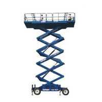
Upright LX41 Service & Parts Manual (188 pages)
Work platform
Brand:
Upright
| Category:
Scissor Lifts
| Size: 20 MB
Table of Contents
Table of Contents
5
Introduction & Specifications
9
Introduction
9
Purpose
9
Scope
9
General Description
9
Platform
9
Controller
9
Elevating Assembly
9
Power Module
9
Control Module
9
Specifications
10
Machine Preparation
11
Preparation for Use
11
Transporting Work Platform
11
By Crane
11
By Truck
11
Preparation for Shipment
12
Storage
12
Preservation
12
Battery
12
Operation
13
Introduction
13
General Functioning
13
Driving
13
With Platform Lowered
13
With Platform Elevated
13
Braking
13
Steering
13
Raising the Platform
14
From the Platform Controls
14
From the Chassis Controls
14
Lowering the Platform
14
Emergency Lowering
14
Leveling the Platform (Outrigger Equipped Machines Only)
14
Design Features
15
Safety Rules and Precautions
15
Controls and Indicators
16
Controller/Platform
16
Chassis
16
Pre-Operation Inspection
18
System Function Inspection
18
Operation
19
Travel with Platform Lowered
20
Steering
20
Leveling the Platform (Outrigger Equipped Machines Only)
20
To Retract Outriggers
20
Raising and Lowering the Platform
20
Travel with Work Platform Elevated
21
Emergency Lowering
21
Switching Fuels
21
(Dual Fuel Only)
21
After Use each Day
21
Parking Brake Release
21
Fold down Guardrails
22
Fold down Procedure
22
Erection Procedure
22
Maintenance
23
Introduction
23
Special Tools
23
Preventative Maintenance
23
Preventative Maintenance Table Key
24
Preventative Maintenance Report
24
Preventative Maintenance Checklist
24
Blocking Elevating Assembly
25
Installation
25
Removal
25
Lubrication
26
Grease Fittings
26
Steering Linkage
26
Battery Maintenance
26
Battery Inspection and Cleaning
26
Torque Hubs
26
Hydraulic Oil and Filter
27
Fluid Level
27
Oil and Filter Replacement
27
Engine Oil and Filter (Figure 4-4)
27
Engine Oil
27
Setting Hydraulic Pressures
28
Pump Set-Up
28
Lift Relief Valve
28
Counterbalance Valves
29
Steering Relief Valves
29
Bidirectional Relief Valves
29
Switch Adjustments
30
Proportional Control Adjustment
30
Procedure
30
Platform down Limit Switches
30
Axle Center Switch
31
Tilt Sensor
31
Hydraulic Manifold
32
Removal
32
Disassembly
32
Cleaning and Inspection
32
Assembly
32
Installation
32
Hydraulic Pump
34
Removal
34
Installation
34
Hydraulic Brakes, Drive Motors, and Hubs
34
Rear Axle
34
Installation
35
Seal Replacement, Brake
35
Seal Replacement, Rear Motor
36
Front Axle 4WD
38
Removal
38
Installation
38
Seal Replacement, Front Motor
40
Axle Cylinder (4WD Only)
42
Removal
42
Seal Replacement
42
Installation
42
Steering Cylinder
44
Removal
44
Seal Replacement
44
Installation
44
Lift Cylinder
46
Removal
46
Seal Replacement
48
Installation
48
Outrigger Cylinder
48
Removal
48
Engine Adjustments
50
Gasoline Engine
50
Idle Speed
50
Governed High Speed
50
Diesel Engine
50
High Speed
50
Propane Engine
51
Leak Idle Adjustment
51
Load Screw Adjustment
51
Filter Replacement
51
Gasoline / Propane Engine
51
Air Filter Element
51
Fuel Filter
51
Diesel Engine
52
Air Filter Element
52
Fuel Filter
52
Torque Specifications
52
Fasteners
52
Hydraulic Components
52
Bolt Torque
52
Hydraulic Component Torque
52
Troubleshooting
53
Introduction
53
General Procedure
53
Troubleshooting Guide
53
Schematics
57
Introduction
57
Electrical Schematics
57
Hydraulic Schematics
57
Component Location
57
Electrical Schematic Legend, Two Wheel Drive, Gasoline / Propane Model (S/N: 1000-1330)
58
Electrical Schematic Legend, Four Wheel Drive, Gasoline / Propane Model (S/N: 1000-1330)
62
Electrical Schematic Legend, Four Wheel Drive, Diesel Model (S/N: 1000-1330)
64
Electrical Schematic Legend, Two Wheel Drive
66
Electrical Schematic Legend, Four Wheel Drive
70
Electrical Schematic Legend, Four Wheel Drive, Diesel Model (after S/N: 1330)
72
Electrical Schematic Legend, Two Wheel Drive
74
Electrical Schematic Legend, Two Wheel Drive
76
Index
93
Final Assembly, LX41, Two Wheel Drive Diesel
98
Final Assembly, LX31, Four Wheel Drive Gas
102
Final Assembly, LX41, Four Wheel Drive Gas
102
Final Assembly, LX31, Four Wheel Drive Diesel
106
Final Assembly, LX41, Four Wheel Drive Diesel
106
Basic Assembly, LX31, Two Wheel Drive
110
Basic Assembly, LX41, Two Wheel Drive
110
Chassis Assembly, LX31/41, Two Wheel Drive
114
Chassis Assembly, LX31/41, Four Wheel Drive
116
Scissor Linkage Assembly, LX
118
Power Module Assembly, LX31/41, Gas
130
Power Module Assembly, LX31/41, Diesel
132
Engine Assembly, LX31/41, Kubota Gas
135
Engine Assembly, LX31/41, Kubota Diesel
138
Slideout Deck Assembly, LX31/41
162
Dual Fuel Option, LX31/41
172
Generator Option Diesel
176
Removable Controller Option Lx
178
Horn Option Lx
180
Outrigger Option Lx
182
Advertisement
Upright LX41 Service Manual (118 pages)
Electric and Bi-Energy Models
Brand:
Upright
| Category:
Lifting Systems
| Size: 9 MB
Table of Contents
Table of Contents
8
Introduction
9
General Description
9
Special Limitations
10
All Models
10
Platform Capacity
10
Manual Force
10
Beaufort Scale
10
Controls and Indicators
11
Pre-Operation & Safety Inspection
12
System Function Inspection
12
Operation
14
Travel with Platform Lowered
14
Travel with Work Platform Elevated
15
Steering
15
Raising and Lowering the Platform
15
Leveling the Platform (Outrigger Equipped Machines Only)
16
Outrigger Switches and Indicator Lights
16
To Level the Platform (Extend the Outriggers)
16
To Retract the Outriggers
16
Emergency Lowering
16
Towing or Winching
17
Parking Brake Release
17
After Use each Day
17
Fold down Guardrails
18
Fold down Procedure
18
Erection Procedure
18
Transporting the Work Platform
19
Preparation for Shipment
19
Lifting by Crane
19
Driving or Winching Onto a Truck or Trailer
19
Maintenance
20
Blocking the Elevating Assembly
20
Brace Installation
20
Brace Removal
20
Hydraulic Fluid
20
Battery Maintenance
21
Engine and Generator (Bienergy Models)
22
Coolant
22
Fuel
22
Oil
22
Preventative Maintenance Schedule
23
Maintenance Table Key
23
Maintenance Report
23
Labels
24
Specifications
26
Section 1
27
Hazard Indicators
28
Table 1-1: Torque Specifications for Hydraulic Components
29
Table 1-2: Torque Specifications for SAE Fasteners
29
Torque Specifications
29
Table 1-3: Torque Specifications for Metric Fasteners, U.S. Customary Units
30
Table 1-4: Torque Specifications for Metric Fasteners, si Units
30
Date Code Identification on Hoses
31
Special Tools
31
Figure 1-1: Upright Connector Kits
32
Figure 1-2: Upright Male Connector
32
Figure 1-3: Upright Female Connector
32
Upright Connectors
32
Figure 1-4: Locking Finger, Upright Connector
33
Figure 1-5: Heavy Duty Upright Connector
33
Hydraulic Manifold Repair
34
Cylinder Repair
35
Electric Motors
36
Figure 1-6: Electric Motor Service
36
Figure 1-7: Electric Motor Brushes
37
Battery Maintenance
38
Table 1-5: Specific Gravity and Battery Voltage
39
Table 1-6: Battery Charging, Upright Electric and Bienergy Machines
40
Table 1-7: Battery Charger Troubleshooting
41
Figure 1-9: Occupied Surface Area
42
Floor Loading
42
Hydraulic Fluid
43
Long Term Storage
44
Section 2
45
Table of Contents
45
Ist of
47
Ist of Igures
47
General Description
48
Component Locations
48
Preventative Maintenance
50
Preventative Maintenance Check List
51
Blocking the Elevating Assembly
52
Installation
52
Removal
52
Lubrication
53
Grease Fittings
53
Torque Hubs
53
Hydraulic Fluid Reservoir and Filter
54
Fluid and Filter Replacement
54
Fluid Level
54
Engine
54
Setting Hydraulic Pressures
55
Lift Relief Valve
55
Steering Relief Valves
55
Switch Adjustments
56
Proximity Switch - Serial Number 4022-4274
56
Proximity Switch Function, Serial Number 4022-4274
56
Test the Proximity Switch, Serial Number 4022-4274
56
Proximity Switch Adjustment, Serial Number 4022-4274
57
Removal and Installation, Serial Number 4022-4274
57
Proximity Switch - Serial Number 4275-Current
58
Test the Proximity Switch, Serial Number 4275-Current
58
Proximity Switch Clearance Adjustment - Serial Number 4275-Current
59
Removal and Installation, Serial Number 4275-Current
59
Level Sensor
60
Proximity Switch Height Adjustment - Serial Number 4275-Current
60
Hydraulic Manifolds
61
Main Hydraulic Manifold
61
Brake Hydraulic Manifold
61
Hydraulic Power Unit
62
Removal
62
Installation
62
Hydraulic Brakes
62
Brake Seal Replacement
63
Installation
63
Torque Hub
64
Torque Hub Removal
64
Torque Hub Installation
65
Torque Hub Seal Replacement
65
Leak Test
65
Pressing Tools
65
Roll and Leak Testing
65
Roll Test
65
Torque Hub Disassembly
66
Torque Hub Assembly
67
Main Assembly
68
Drive Motors
70
Removal
70
Installation
70
Drive Motor Brushes
70
Pump Motor
70
Steering Cylinder
71
Removal
71
Seal Replacement
71
Installation
71
Lift Cylinders
72
Removal
72
Seal Replacement
72
Installation
72
Outrigger Cylinder (Optional)
74
Removal
74
Seal Replacement
74
Installation
74
Generator, Bi-Energy Models Only
76
Drive Belt Adjustment
76
Section 3
77
3-1 Introduction
78
Adjustment Procedures
78
Checking Pump Pressures
78
General Procedure
78
Technical Support
78
Troubleshooting Procedures
78
Electric Truth Tables
79
Electrical Schematics
79
Outrigger Option
81
Hydraulic Truth Table
82
Troubleshooting the MOS90
83
When a Flash Error Occurs
83
Using the Calibrator
83
Calibrator Settings
84
Upright Traction Controller Display
84
MOS90 Fault Finding Flow Charts
85
Activating "TEST
91
Section 4
93
Electrical Schematic, LX Bi-Energy Serial # 4022-4274
94
Electrical Schematic, LX Electric: Serial # 4022-4274
98
Electrical Schematic, LX Bi-Energy - Outriggers
102
Electrical Schematic, LX Electric - Outriggers
104
Wire Routing
106
Electric
106
Bi-Energy
107
Control Box, Electric
108
Control Box, Bi-Energy
109
Upper Controls, Electric
110
Outrigger Option
112
Hydraulic Schematic
112
Hose Routing
113
Component Identification
114
Upright LX41 Service Manual (120 pages)
Brand:
Upright
| Category:
Lifting Systems
| Size: 7 MB
Table of Contents
Forward
5
Workshop Procedures
5
Special Information
5
Introduction & Specifications
5
Table of Contents
7
Introduction
11
Purpose of Equipment
11
Purpose
11
Special Limitations
11
Scope
11
Specifications
11
General Description
11
Platform
11
Controller
11
Elevating Assembly
11
Table 1-1: Work Platform Specifications
12
Machine Preparation & Operation
14
Figure 2-1: Chassis Control Panel
14
Machine Preparation & Operation
15
Figure 2-2: Controller
15
Figure 2-3: Tilt Sensor
15
Figure 2-5: Parking Brake Release Button
17
From the Chassis Controls
18
Operation
19
Lowering the Platform
19
From the Platform Controls
19
Machine Preparation & Operation
20
Table 2-1: Controls and Indicators
20
Figure 2-6: Controls and Indicators
21
Fold down Guardrails
22
Erection Procedure
22
Figure 2-7: Fold down Guardrails
22
Double Deck Fold down Procedure
23
Erection Procedure
23
Figure 2-8: Fold down Guardrails (Double Deck)
23
Maintenance
25
Introduction
25
General Procedures
25
Date Code Identification on Hoses
25
Special Tools
25
Deutsch Connectors
26
Figure 3-1: Deutsch Connector Kit, Small
26
Figure 3-3: Plugs and Receptacles, Deutsch Connectors
26
Male Connector (Plug)
27
Female Connector (Receptacle)
27
Releasing Locking Fingers
27
Figure 3-4: Locking Finger, Deutsch Connector
27
Figure 3-5: Heavy Duty Deutsch Connector
27
Table 3-1: Preventative Maintenance Checklist
29
Figure 3-6: Blocking Elevating Assembly
30
Figure 3-7: Lubrication Chart
31
Oil and Filter Replacement
32
Figure 3-8: Hydraulic Oil Tank and Filter
32
Setting Hydraulic Pressures
33
Steering Relief Valves
33
Figure 3-9: Hydraulic Pump
33
Figure 3-10: Valve Manifold
33
Switch Adjustments
34
Proportional Control Adjustment
34
Proportional Drive Control
34
Platform down Limit Switches
35
Tilt Sensor
35
Blocking Elevating Assembly
35
Hydraulic Manifold
36
Removal
36
Disassembly
36
Cleaning and Inspection
36
Assembly
36
Installation
36
Hydraulic Power Unit
38
Removal
38
Installation
38
Hydraulic Brakes
38
Brake Seal Replacement
39
Assembly
39
Installation
39
Installation
40
Drive Motors
40
Removal
40
Drive Motor Brushes
40
Torque Hub
41
Removal
41
Installation
48
Maintenance
50
Table 3-2: Torque Specifications for Fasteners
50
Table 3-3: Torque Specifications for Hydraulic Components
50
Introduction
51
General Procedure
51
Troubleshooting
52
Table 4-1: Trouble Shooting Guide: Electrical Schematics
52
Troubleshooting Hydraulic
55
Table 1: Troubleshooting Guide: Hydraulic Schematics
55
Figure 4-1: MOS90 Calibrator LED Segments
56
Table 4-2: Calibrator Settings
57
Table 4-3: Calibrator Display
57
MOS90 Fault Finding Flow Charts
58
4.9 Activating "Test
64
Figure 4-2: MOS90 17 Way Connector Pinout Designation
64
Figure 4-3: Upright Tachometer Board
65
Schematics
67
Introduction
67
Hydraulics
67
Electrical
67
5.3 Component Identification
67
Schematics
68
Illustrated Parts Breakdown
75
Advertisement
Upright LX41 Operator's Manual (36 pages)
LX Series
Brand:
Upright
| Category:
Scissor Lifts
| Size: 4 MB
Table of Contents
Deutsch
4
Table of Contents
4
Introduction
5
General Description
6
Introduction.
6
Special Limitations
6
Controls and Indicators
7
Pre-Operation & Safety Inspection
8
Pre-Operation & Safety Inspection
9
System Function Inspection
9
Operation
10
To Retract the Outriggers
12
Emergency Lowering
13
Towing or Winching
14
After Use each Day.
15
Fold down Guardrails
15
Transporting the Work Platform
16
Maintenance
17
Preventative Maintenance Schedule
20
Labels
22
Specifications
24
Français
26
Introduction
27
Description Générale
27
Limitations Particulières
28
Tous Les Modèles
28
Capacité de la Plate-Forme
28
Force Manuelle
28
Échelle de Beaufort
28
Alarme de Surcharge de Levage
28
Commandes Et Indicateurs
29
Inspection de Sécurité Avant Utilisation
30
Essai de Fonctionnement des Systèmes
30
Utilisation
32
Déplacement Avec la Plate-Forme Abaissée
32
Déplacement Avec la Plate-Forme Élevée
33
Direction
33
Élévation Et Abaissement de la Plate-Forme
33
Mise de Niveau de la Plate-Forme
34
(Machines Équipées de Stabilisateurs Seulement)
34
Commutateurs Et Témoins de Stabilisateurs
34
Mise de Niveau de la Plate-Forme (Extension des Stabilisateurs)
34
Rétraction des Stabilisateurs
34
Abaissement D'urgence
35
LX31 Et LX41
35
Lx50
35
Remorquage Ou Treuillage
36
Desserrage de Frein de Stationnement
36
Après Utilisation, Tous Les Jours
36
Garde-Corps Rabattables
36
Repli des
36
Upright LX41 Operator's Manual (41 pages)
Brand:
Upright
| Category:
Scissor Lifts
| Size: 5 MB
Table of Contents
Safety Rules
2
System Function Inspection
3
Operation
5
Raising and Lowering the Platform
6
Travel with Work Platform Elevated
6
Emergency Lowering
6
Fold down Guardrails
7
Erection Procedure
7
Transporting Work Platform
7
Installation
8
Battery Maintenance
8
Specifications
10
Version Française
11
Règles de Sécurité
11
Élévation Et Abaissement de la Plate-Forme
15
Garde-Corps Rabattables
16
Transport de la Plate-Forme Élévatrice
16
Par Camion
16
Entretien de la Batterie
17
Entretien Courant
18
Fiche Technique
19
Bedienung
24
Nach Täglichem Gebrauch
25
Umklappen der Schutzgeländer
26
Transport der Arbeitsbühne
26
Versión en Español
31
Reglas de Seguridad
31
Operación
34
Mantenimiento
37
Mantenimiento de Rutina
38
Especificaciones
39
Upright LX41 Operator's Manual (25 pages)
LX Electric & BiEnergy
Brand:
Upright
| Category:
Scissor Lifts
| Size: 2 MB
Table of Contents
Safety Rules
2
Travel with Platform Lowered
5
Operation
5
Raising and Lowering the Platform
5
Travel with Work Platform Elevated
6
Emergency Lowering
6
After Use each Day
6
Fold down Guardrails
7
Transporting Work Platform
8
Especificaciones
8
Mantenimiento de Rutina
9
Installation
9
Battery Maintenance
9
Routine Service
10
Mantenimiento de la Batería
10
Version Française
12
Règles de Sécurité
12
Operación
14
Versión en Español
17
Reglas de Seguridad
17
Garde-Corps Rabattables
17
Transport de la Plate-Forme Élévatrice
18
Par Camion
18
Technische Daten
18
Entretien de la Batterie
19
Entretien Courant
20
Transport der Arbeitsbühne
21
Fiche Technique
21
Sicherheitsinspektion vor Inbetriebnahme
23
Betrieb
24
Upright LX41 Operator's Manual (10 pages)
Brand:
Upright
| Category:
Lifting Systems
| Size: 2 MB
Table of Contents
Table of Contents
4
Introduction
5
Outrigger Option
5
General Description
5
Controls and Indicators
6
Pre-Operation & Safety Inspection
6
System Function Inspection
7
Operation
8
Travel with Platform Lowered
8
Travel with Work Platform Elevated
8
Steering
8
Raising and Lowering the Platform
9
Leveling the Platform (Outrigger Equipped Machines Only)
9
To Level the Platform (Extend the Outriggers)
9
Outrigger Switches and Indicator Lights
9
To Retract the Outriggers
9
Emergency Lowering
10
Towing or Winching
10
Parking Brake Release
10
After Use each Day
10
Fold down Guardrails
10
Erection Procedure
10
Upright LX41 Operator's Manual (12 pages)
SERIAL NO. 4022 to Current
Brand:
Upright
| Category:
Lifting Systems
| Size: 3 MB
Table of Contents
Table of Contents
4
Introduction
5
Controls and Indicators
6
Pre-Operation & Safety Inspection
7
Operation
8
Emergency Lowering
11
Towing or Winching
12
Upright LX41 Operator's Manual (12 pages)
LX Electric & Bi-Energy
Brand:
Upright
| Category:
Lifting Systems
| Size: 1 MB
Table of Contents
Operation
4
Fold down Guardrails
6
Transporting Work Platform
7
Maintenance
8
Specifications
12
Upright LX41 Operator's Manual (12 pages)
LX series
Brand:
Upright
| Category:
Lifting Systems
| Size: 1 MB
Table of Contents
Operation
4
Fold down Guardrails
6
Maintenance
8
Specifications
12
Advertisement
Related Products
Upright LX31
Upright LX Electric
Upright LX Bi-Energy
Upright LX50
Upright 6013
Upright 9300
Upright AB-46 Bi-Energy
Upright ab62
Upright MX15
Upright MX19
Upright Categories
Lifting Systems
Scissor Lifts
Boom Lifts
Construction Equipment
Health Care Products
More Upright Manuals
Login
Sign In
OR
Sign in with Facebook
Sign in with Google
Upload manual
Upload from disk
Upload from URL