
Related Manuals for Tektronix KEITHLEY 8010


Summary of Contents for Tektronix KEITHLEY 8010
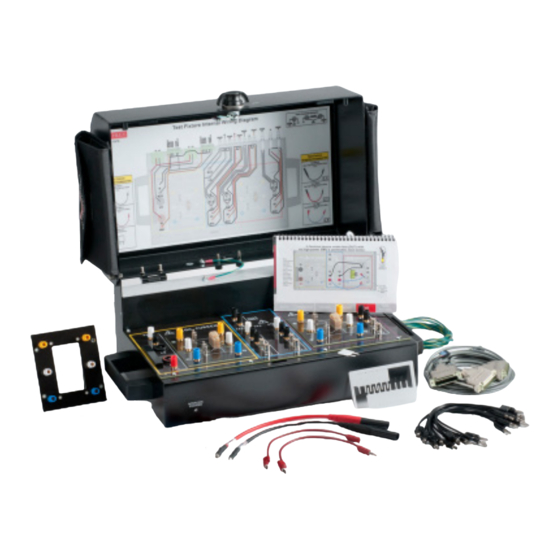
- Page 1 www.tek.com\keithley Model 8010 High Power Device Test Fixture User’s Manual 8010-900-01 Rev. C / March 2017 *P8010-900-01C* 8010-900-01C A Great er Me a s ure of C on f i de nc e...
- Page 2 Model 8010 High Power Device Test Fixture User's Manual © 2017, Keithley Instruments Cleveland, Ohio, U.S.A. All rights reserved. Any unauthorized reproduction, photocopy, or use of the information herein, in whole or in part, without the prior written approval of Keithley Instruments is strictly prohibited. All Keithley Instruments product names are trademarks or registered trademarks of Keithley Instruments.
- Page 3 Safety precautions The following safety precautions should be observed before using this product and any associated instrumentation. Although some instruments and accessories would normally be used with nonhazardous voltages, there are situations where hazardous conditions may be present. This product is intended for use by qualified personnel who recognize shock hazards and are familiar with the safety precautions required to avoid possible injury.
- Page 4 For safety, instruments and accessories must be used in accordance with the operating instructions. If the instruments or accessories are used in a manner not specified in the operating instructions, the protection provided by the equipment may be impaired. Do not exceed the maximum signal levels of the instruments and accessories. Maximum signal levels are defined in the specifications and operating information and shown on the instrument panels, test fixture panels, and switching cards.
-
Page 5: Table Of Contents
Installing a device in the TO socket ..................3-5 Using the insulating plug ...................... 3-6 Using the 8010-DTB-CT....................... 3-6 Installing Tektronix socket adapters ..................3-7 Measurement considerations ....................3-7 Local and remote sense measurements ................... 3-7 Suppressing device oscillations ....................3-10 Optimizing connections for high current DC pulses .............. - Page 6 Table of Contents Model 8010 High Power Device Test Fixture User's Manual Off-state MOSFET characterization of a power MOSFET ........4-1 Introduction .......................... 4-1 Equipment needed for this example ..................4-2 Device connections ......................4-2 Install the device and make connections ................4-6 Set up communication......................
- Page 7 Model 8010 High Power Device Test Fixture User's Manual Table of Contents Power MOSFET capacitance (Ciss, Coss, Cgs, Cds) CVU-200-KIT measurement ....7-6 Install the device and make connections ................7-7 Power MOSFET capacitance CVU-3K-KIT measurement ............7-7 Power MOSFET capacitance CVU-200-KIT measurement ............. 7-14 Set up communication......................
-
Page 8: Model 8010 Overview
Section 1 Model 8010 overview In this section: Model 8010 overview..............1-1 Extended warranty..............1-2 Organization of manual sections ..........1-2 Contact information ..............1-3 Unpacking and inspection ............1-3 Accessories ................1-3 Characteristics ................1-3 Model 8010 overview Thank you for choosing a Keithley Instruments product. The Model 8010 High Power Device Test Fixture provides a safe, low noise, complete environment for testing a variety of packaged device types. -
Page 9: Extended Warranty
TO-247 devices and is limited to 1000 V and the maximum rated current of the test fixture. Additionally, the 8010-DTB-CT Curve Tracer Adapter Test Board allows you to use the same socket style installed in Tektronix Series Curve Tracers. Extended warranty Additional years of warranty coverage are available on many products. -
Page 10: Contact Information
Model 8010 High Power Device Test Fixture User's Manual Section 1: Model 8010 overview Contact information If you have any questions after you review the information in this documentation, please contact your local Keithley Instruments office, sales partner, or distributor. You can also call the corporate headquarters of Keithley Instruments (toll-free inside the U.S. -
Page 11: Connecting Instruments
Section 2 Connecting instruments In this section: Rear panel overview ..............2-1 Installing the test boards ............2-3 Using the interlock ..............2-5 Rear panel connections ............2-5 Using the access port on the Model 8010 ......2-12 Rear panel overview Instrument connections are made to the rear panel of the Model 8010. - Page 12 Section 2: Connecting instruments Model 8010 High Power Device Test Fixture User's Manual The access port on the lid can be used to bring in connections for external instrumentation. The Model 2657 connectors provide sense HI, HI, LO, and sense LO input connections for the Model 2657 instruments.
-
Page 13: Installing The Test Boards
In addition, you can purchase the 8010-DTB-220 Device Test Board for use with three-terminal TO-220 or TO-247 devices. This board is limited to 1000 V. The 8010-DTB-CT Curve Tracer Adapter Test Board is also available, and allows you to use the same socket style installed in Tektronix Series Curve Tracers. - Page 14 Section 2: Connecting instruments Model 8010 High Power Device Test Fixture User's Manual Tool required • Medium Phillips head screwdriver Assembly instructions If you are customizing the 8010-CTB Customizable Test Board, make customizations before installing it in the Model 8010. 1.
-
Page 15: Using The Interlock
Model 8010 High Power Device Test Fixture User's Manual Section 2: Connecting instruments Using the interlock The Model 8010 can be connected to instruments that can output hazardous live voltages. To ensure operator safety, the Model 8010 provides a built-in interlock switch. The interlock switch is engaged when the Model 8010 lid is closed and latched. -
Page 16: Model 2611 And Model 2612 Connections
Section 2: Connecting instruments Model 8010 High Power Device Test Fixture User's Manual Model 2611 and Model 2612 connections The Model 8010 includes internal protection circuitry for the Model 2611 and 2612 SMUs. If there is a device under test (DUT) failure, this circuitry protects the SMUs from high voltage from the Model 2657. - Page 17 Model 8010 High Power Device Test Fixture User's Manual Section 2: Connecting instruments Figure 3: Model 8010 to Model 2611 or 2612 rear panel connections 8010-900-01 Rev. C / March 2017...
-
Page 18: Model 2635 And Model 2636 Connections
Section 2: Connecting instruments Model 8010 High Power Device Test Fixture User's Manual Model 2635 and Model 2636 connections The Model 8010 includes internal protection circuitry for the Model 2635 and 2636 SMUs. In the case of a device under test (DUT) failure, this circuitry protects the SMUs from high voltage from the Model 2657. -
Page 19: Model 2651 Connections
Model 8010 High Power Device Test Fixture User's Manual Section 2: Connecting instruments Model 2651 connections There is no safety interlock on the Model 2651 — the safety interlock is not necessary because output voltage of the Model 2651 is below hazardous levels. The CA-558-2 cable is shown here in case you want to use Output Enable to shut off the output when the Model 8010 lid is opened. -
Page 20: Model 2657 Connections
Section 2: Connecting instruments Model 8010 High Power Device Test Fixture User's Manual Model 2657 connections Figure 6: Model 8010 to Model 2657 rear panel connections 2-10 8010-900-01 Rev. C / March 2017... -
Page 21: Model 4200 And Model 4210-Smu Connections
Model 8010 High Power Device Test Fixture User's Manual Section 2: Connecting instruments Model 4200 and Model 4210-SMU connections The Model 8010 includes internal protection circuitry for the Models 4200 and 4210-SMU. In the case of a device under test (DUT) failure, this circuitry protects the SMUs from high voltage from the Model 2657. -
Page 22: Internal Protection Circuitry
Section 2: Connecting instruments Model 8010 High Power Device Test Fixture User's Manual The 4200-PA preamplifier should be removed when the 4200-SCS is connected to the 8010 or to the CVU-3K-KIT bias tees. Internal protection circuitry The Model 8010 includes internal protection circuitry that protects instruments in applications where a device breakdown or other potential failure could connect the high-voltage output of a Model 2657 high-voltage SMU to a lower voltage SMU. - Page 23 Model 8010 High Power Device Test Fixture User's Manual Section 2: Connecting instruments If you want to use the oscilloscope voltage probe to monitor the instrument output, connect the probe to the Guard terminal to avoid loading the device under test. 8010-900-01 Rev.
-
Page 24: Working With Devices And Instruments
Section 3 Working with devices and instruments In this section: Safety information ..............3-1 Device test boards ..............3-2 Installing a device in the axial posts ......... 3-4 Installing a device in the TO socket .......... 3-5 Using the insulating plug ............3-6 Using the 8010-DTB-CT ............ -
Page 25: Device Test Boards
Section 3: Working with devices and instruments Model 8010 High Power Device Test Fixture User's Manual Device test boards The Model 8010-DTB, 8010-DTB-220, 8010-DTB-CT (curve tracer), and 8010-CTB (customizable test board), device test boards include sockets for three-terminal and axial-lead devices (see the next graphics). - Page 26 Model 8010 High Power Device Test Fixture User's Manual Section 3: Working with devices and instruments Figure 10: 8010-DTB-CT Figure 11: 8010-CTB The socket has true remote sense connections to each pin, with two binding posts connected to each terminal of the device. One set of binding posts is intended for force connections and the other for sense connections.
-
Page 27: Installing A Device In The Axial Posts
Section 3: Working with devices and instruments Model 8010 High Power Device Test Fixture User's Manual When making connections: • Connect force leads to binding posts 4, 5, and 6 • Connect sense leads to binding posts 1, 2, and 3 These pins are connected internally to each other (binding post 1 to post 4, 2 to 5, and 3 to 6). -
Page 28: Installing A Device In The To Socket
Model 8010 High Power Device Test Fixture User's Manual Section 3: Working with devices and instruments Figure 13: Model 8010-DTB and DTB-220 axial leads and TO socket Installing a device in the TO socket This section explains how to install a device in the TO (transistor outline) socket of the 8010-DTB or 8010-DTB-220 board. -
Page 29: Using The Insulating Plug
You can use the Model 8010-DTB-CT to test 2-terminal devices and 3-terminal devices. The test board can be used with device adapters for Tektronix curve tracers (see next figures). Before installing a device adapter on a device test board, make sure that you have the device adapter bottom terminals lined up correctly with the test board. -
Page 30: Installing Tektronix Socket Adapters
Model 8010 High Power Device Test Fixture User's Manual Section 3: Working with devices and instruments Installing Tektronix socket adapters The next graphic is a device test board. Notice that the test board contains the letters C, B, and E, which also corresponds to the function of each terminal. - Page 31 Section 3: Working with devices and instruments Model 8010 High Power Device Test Fixture User's Manual The 2-wire sensing method requires only two test leads. However, as shown in the following figure, test lead resistance can seriously affect the accuracy of 2-wire resistance measurements, particularly when measuring smaller resistance values.
- Page 32 Model 8010 High Power Device Test Fixture User's Manual Section 3: Working with devices and instruments The 4-wire sensing method, as shown in the following figure, minimizes or eliminates the effects of lead resistance by measuring the voltage across the resistor under test with a second set of test leads.
-
Page 33: Suppressing Device Oscillations
Section 3: Working with devices and instruments Model 8010 High Power Device Test Fixture User's Manual Suppressing device oscillations During on-state characterization of MOSFET and IGBT devices, high-current pulses that travel through the channel of the device may cause the device gate to oscillate. The instability of the gate voltage will result in unstable measurements through the device channel. - Page 34 Model 8010 High Power Device Test Fixture User's Manual Section 3: Working with devices and instruments If you are using a four-wire configuration, the sense lead of the SMU will need to be connected to the same side of the resistor as the source lead. To connect both the sense and source leads to the same side of the resistor, stack the ends of the force and sense lead jumpers together, then connect them to the customer-supplied alligator clip.
-
Page 35: Optimizing Connections For High Current Dc Pulses
Section 3: Working with devices and instruments Model 8010 High Power Device Test Fixture User's Manual Optimizing connections for high current DC pulses The Model 8010 is capable of carrying up to 100 A pulses from two Model 2651 SMU instruments. You can connect two Model 2651 SMU instruments to the Model 8010, plus, the SMU instruments can be connected in parallel. - Page 36 Model 8010 High Power Device Test Fixture User's Manual Section 3: Working with devices and instruments The guard terminal is useful for maintaining low-leakage measurements if you are using the customized test board or if you are monitoring the test through the access port on the rear of the cover.
- Page 37 Section 3: Working with devices and instruments Model 8010 High Power Device Test Fixture User's Manual The next figures show how a cable guard can eliminate leakage current through the insulators in a test fixture. In these figures, leakage current (I ) flows through the insulators (R and R ) to LO,...
-
Page 38: Making High Voltage C-V Measurements
Model 8010 High Power Device Test Fixture User's Manual Section 3: Working with devices and instruments Making high voltage C-V measurements The bias tees can hold charge and it is necessary to discharge them before opening the cover of the Model 8010 and making changes to the cable connectors. See Discharge bias tee and system capacitance (on page 3-28) later in this section. -
Page 39: Making Measurements Through The Bias Tee
Section 3: Working with devices and instruments Model 8010 High Power Device Test Fixture User's Manual • CVU-3K-KIT The kit includes one 3000 V bias tee and two 200 V bias tees, cables, connectors, and a discharge probe. It supports C-V measurements with DC bias at up to three device terminals (one terminal up to 3000 V and the other up to 200 V)(refer to the CVU-3K-KIT instructions;... - Page 40 Model 8010 High Power Device Test Fixture User's Manual Section 3: Working with devices and instruments DC measurements (leakage current) The default state of the bias tee switch optimizes DC measurements. AC and DC measurements (capacitance measurements) Low Current (device in off-state): Results in the most accurate AC and DC measurements possible using the bias tee by adding isolation to the path of the DC instrument.
- Page 41 Section 3: Working with devices and instruments Model 8010 High Power Device Test Fixture User's Manual Isolating the C-V instrument and SMU from each other is not perfect or stable across the range of frequencies used by the C-V instrument. Balancing the performance of DC I-V and AC C-V signal path needs can result in compromises in the usable frequency range for AC C-V measurements and the minimum current sensitivity for DC low current measurements.
- Page 42 Model 8010 High Power Device Test Fixture User's Manual Section 3: Working with devices and instruments Table: Bias tee kit operating modes overview Mode/block Application AC switch DC switch Control voltage diagram state state I-V mode (on page Use for best DC low current 0 V (default Open Closed...
- Page 43 Section 3: Working with devices and instruments Model 8010 High Power Device Test Fixture User's Manual C-V mode The off-state C-V measurement mode (DC bias current <= 1 mA) is the preferred mode for most C-V measurements. This mode achieves an AC measurement frequency range of 10 kHz – 1 MHz by opening the bias tee DC switch.
- Page 44 Model 8010 High Power Device Test Fixture User's Manual Section 3: Working with devices and instruments The following graphic shows how to use the external bias tees for making up to 3 kV capacitance measurement connections. Figure 29: CVU-3K-KIT 2-Terminal measurement connections 8010-900-01 Rev.
- Page 45 Section 3: Working with devices and instruments Model 8010 High Power Device Test Fixture User's Manual The following graphic shows how to use the external bias tees for making up to 200 volt capacitance measurement connections (400 V differential). Figure 30: CVU-200-KIT 2-Terminal measurement connections 3-22 8010-900-01 Rev.
- Page 46 Model 8010 High Power Device Test Fixture User's Manual Section 3: Working with devices and instruments The ground wires must be attached to a known protective earth (safety ground) before powering on instruments. Failure to attach the ground wires to a known protective earth may result in electric shock.
- Page 47 Section 3: Working with devices and instruments Model 8010 High Power Device Test Fixture User's Manual The following shows a two-terminal axial DUT with a series 2600 and 4200 GNDU connected (local sense). This configuration can be used for testing two-terminal TO-247 devices, as well. When testing two-terminal TO-247 devices, remove the plug from the socket, if inserted.
- Page 48 Model 8010 High Power Device Test Fixture User's Manual Section 3: Working with devices and instruments The next figure shows how to perform a short connection test without a device inserted and how to install a short between the fixture terminals: Figure 34: Model 8010 CVU-3K-KIT 2-term DUT terminal short connection The following shows a two-terminal axial DUT.
-
Page 49: Optimizing Cables And Connections For High Voltage C-V Measurements
Section 3: Working with devices and instruments Model 8010 High Power Device Test Fixture User's Manual The next figure shows how to perform an open connection test without a device inserted: Figure 36: Model 8010 CVU-200-KIT 2-term DUT terminal open connection The next figure shows how to perform a short connection test without a device inserted and how to install a short between the fixture terminals: Figure 37: Model 8010 CVU-200-KIT 2-term DUT terminal short connection... - Page 50 Model 8010 High Power Device Test Fixture User's Manual Section 3: Working with devices and instruments Stray capacitance, resistance, and inductance in the test setup cause measurement errors. These errors will vary with setup and their impact varies with frequency. To remove these errors from the measurement, perform connection compensation.
-
Page 51: Discharge Bias Tee And System Capacitance
Section 3: Working with devices and instruments Model 8010 High Power Device Test Fixture User's Manual Figure 38: Model 4210-CVU impedance measurement system Discharge bias tee and system capacitance The capacitance of the bias tees in the Models CVU-200-KIT and CVU-3K-KIT can hold charge. Devices with sufficient capacitance can also hold charge. - Page 52 Model 8010 High Power Device Test Fixture User's Manual Section 3: Working with devices and instruments Use the Model 8020-DP to discharge system capacitance Figure 40: 8020-DP High Voltage Discharge Probe Prior to connecting the Model 8020-DP discharge probe, be sure that the Model 8010 has been connected to protective earth.
- Page 53 Section 3: Working with devices and instruments Model 8010 High Power Device Test Fixture User's Manual 2. Make sure that grounding wires are connected to protective earth (safety ground) screw terminals of the remote bias tee mounting bracket (see illustration below). Figure 42: Grounding the remote bias tee mounting bracket 3-30 8010-900-01 Rev.
- Page 54 Model 8010 High Power Device Test Fixture User's Manual Section 3: Working with devices and instruments 3. Connect the 8020-DP discharge probe ground cable to the protective earth (safety ground) screw terminal on the bias tee. Nothing else should be connected to the protective earth (safety ground) screw terminal. Do not stack protective earth cables.
- Page 55 Section 3: Working with devices and instruments Model 8010 High Power Device Test Fixture User's Manual 4. Open the 8010 test fixture cover. 5. While holding the discharge probe handle, use the probe to contact the terminals on the device test board that contact the 2657 HI and SHI terminals.
- Page 56 Model 8010 High Power Device Test Fixture User's Manual Section 3: Working with devices and instruments If there is no cable connected to the HI and SHI connections of the 2657, use the discharge probe to contact the center conductor of the HI and SHI BNC connectors. Hold there for at least one second to safely discharge system capacitance.
-
Page 57: Off-State Mosfet Characterization Of A Power Mosfet
Section 4 Off-state MOSFET characterization of a power MOSFET In this section: Introduction ................4-1 Equipment needed for this example ......... 4-2 Device connections ..............4-2 Install the device and make connections ........4-6 Set up communication .............. 4-7 BVdss measurement ..............4-8 Idss measurement .............. -
Page 58: Equipment Needed For This Example
Section 4: Off-state MOSFET characterization of a power MOSFET Model 8010 High Power Device Test Fixture User's Manual Equipment needed for this example • One Model 8010 High Power Test Fixture with the Model 8010-DTB board installed on the high voltage side of the test fixture (see Installing the test boards (on page 2-3) for more information) - Page 59 Model 8010 High Power Device Test Fixture User's Manual Section 4: Off-state MOSFET characterization of a power MOSFET Figure 48: Model 8010 to Model 2611 or 2612 rear panel connections for MOSFET application example 8010-900-01 Rev. C / March 2017...
- Page 60 Section 4: Off-state MOSFET characterization of a power MOSFET Model 8010 High Power Device Test Fixture User's Manual Figure 49: Model 8010 to Model 2635 or 2636 rear panel connections for MOSFET application example 8010-900-01 Rev. C / March 2017...
- Page 61 Model 8010 High Power Device Test Fixture User's Manual Section 4: Off-state MOSFET characterization of a power MOSFET Figure 50: Model 8010 to Model 2657 rear panel connections 8010-900-01 Rev. C / March 2017...
-
Page 62: Install The Device And Make Connections
Section 4: Off-state MOSFET characterization of a power MOSFET Model 8010 High Power Device Test Fixture User's Manual Install the device and make connections To install a device in the Model 8010 and connect instruments to the device: 1. Ensure that the Model 8010-DTB test board is installed. Refer to Installing the test boards page 2-3). -
Page 63: Set Up Communication
Model 8010 High Power Device Test Fixture User's Manual Section 4: Off-state MOSFET characterization of a power MOSFET Set up communication The communication setup is illustrated in the following diagram. This application can be run using any of the supported communication interfaces for the instruments. Figure 52: Remote interface and TSP-Link communications setup Item Description Notes... -
Page 64: Bvdss Measurement
Section 4: Off-state MOSFET characterization of a power MOSFET Model 8010 High Power Device Test Fixture User's Manual BVdss measurement The example code is designed to be run from Test Script Builder. It can also be run from other programming environments, such as Microsoft ®... -
Page 65: Example Code
Model 8010 High Power Device Test Fixture User's Manual Section 4: Off-state MOSFET characterization of a power MOSFET Example code --[[ Title: FET Drain-Source Breakdown Voltage Description: This script measures the drain-source breakdown voltage (BVdss) of a FET. --]] --[[ BVdss(gateV, drainI, measDelay, igLimit, vdLimit, numNPLC) Description: This function uses the Model 2657 to force a current from drain to source. -
Page 66: Example Usage
Section 4: Off-state MOSFET characterization of a power MOSFET Model 8010 High Power Device Test Fixture User's Manual smua.measure.delay = measDelay --Run the test. node[2].smua.source.output = 1 smua.source.output = 1 I,V = smua.measure.iv() smua.source.output = 0 node[2].smua.source.output = 0 print("Test current:", I) print("Measured voltage:", V) Example usage The function in this script allows updates to the test parameters without rewriting or re-running the... -
Page 67: Idss Measurement
Model 8010 High Power Device Test Fixture User's Manual Section 4: Off-state MOSFET characterization of a power MOSFET Idss measurement This example: • Performs the I measurement, where the drain-to-source voltage (V ) is swept and leakage current measurements are made while the FET is in the off-state. •... -
Page 68: Example Code
Section 4: Off-state MOSFET characterization of a power MOSFET Model 8010 High Power Device Test Fixture User's Manual Example code --[[ Title: FET Drain-to-Source Leakage Current Measurement Sweep Description: This script measures the drain current while the drain voltage is sweeping linearly and under a 0 V gate bias. --]] --[[ Idss(gateV, startV, stopV, numSteps, measDelay, measRange, iLimit, numNPLC) - Page 69 Model 8010 High Power Device Test Fixture User's Manual Section 4: Off-state MOSFET characterization of a power MOSFET --Configure source parameters for the drain SMU. smua.source.func = smua.OUTPUT_DCVOLTS smua.source.levelv = 0 smua.source.limiti = iLimit if math.abs(startV) > math.abs(stopV) then smua.source.rangev = startV else smua.source.rangev = stopV --Configure measurement parameters for the drain SMU.
-
Page 70: Example Usage
Section 4: Off-state MOSFET characterization of a power MOSFET Model 8010 High Power Device Test Fixture User's Manual Example usage The functions in this script allow updates to the test parameters without rewriting or re-running the script. To run the test, call the Idss() function, passing in the appropriate values for test parameters. Idss() parameters Parameter Units... - Page 71 Model 8010 High Power Device Test Fixture User's Manual Section 4: Off-state MOSFET characterization of a power MOSFET Figure 53: Example output data 8010-900-01 Rev. C / March 2017 4-15...
-
Page 72: Axial-Lead Device High Current Test
Section 5 Axial-lead device high current test In this section: Introduction ................5-1 Equipment needed ..............5-1 Connect the instrument to the Model 8010 ....... 5-2 Install the device and make connections ........5-3 Set up communication .............. 5-3 Example program code ............5-4 Example program usage ............ -
Page 73: Connect The Instrument To The Model 8010
Section 5: Axial-lead device high current test Model 8010 High Power Device Test Fixture User's Manual Connect the instrument to the Model 8010 Connect the Model 8010 to the Model 2651 as shown in the graphic below. This example does not use the interlock, although the connections for the interlock are shown in the following graphic. -
Page 74: Install The Device And Make Connections
Model 8010 High Power Device Test Fixture User's Manual Section 5: Axial-lead device high current test Install the device and make connections To install a device in the Model 8010 and connect instruments to the device: 1. Ensure that the Model 8010-DTB or Model 8010-DTB-220 device test board is installed. Refer to Installing the test boards (on page 2-3) for information on installing the device test boards. -
Page 75: Example Program Code
Section 5: Axial-lead device high current test Model 8010 High Power Device Test Fixture User's Manual Example program code The example code is designed to be run from Test Script Builder. It can also be run from other programming environments, such as Microsoft ®... - Page 76 Model 8010 High Power Device Test Fixture User's Manual Section 5: Axial-lead device high current test --[[ Title: Fast ADC Usage Description: This script is designed to output pulses and capture both the current and the voltage of the pulse using the fast ADC of the Model 2651 High Power System SourceMeter instrument.
- Page 77 Section 5: Axial-lead device high current test Model 8010 High Power Device Test Fixture User's Manual -- Prepare the reading buffers smua.nvbuffer1.clear() smua.nvbuffer1.collecttimestamps smua.nvbuffer1.collectsourcevalues smua.nvbuffer1.fillmode = smua.FILL_ONCE smua.nvbuffer2.clear() smua.nvbuffer2.collecttimestamps smua.nvbuffer2.collectsourcevalues smua.nvbuffer2.fillmode = smua.FILL_ONCE -- Cannot use source values with async measurements -- Configure the Pulsed Sweep setup ----------------------------------- -- Timer 1 controls the pulse period...
- Page 78 Model 8010 High Power Device Test Fixture User's Manual Section 5: Axial-lead device high current test --[[ Name: CapturePulseI(pulseLevel, pulseWidth, pulseLimit, numPulses) Description: This function outputs current pulses with a 1% duty cycle and performs measurements using the fast ADC to capture each pulse in its entirety. At the conclusion of the pulse train, the data is returned to the instrument console in a Microsoft Excel compatible format.
- Page 79 Section 5: Axial-lead device high current test Model 8010 High Power Device Test Fixture User's Manual ----------------------------------- -- Timer 1 controls the pulse period trigger.timer[1].count = numPulses - 1 -- 1% Duty Cycle trigger.timer[1].delay = pulseWidth / 0.01 trigger.timer[1].passthrough = true trigger.timer[1].stimulus = smua.trigger.ARMED_EVENT_ID -- Timer 2 controls the pulse width...
-
Page 80: Example Program Usage
Model 8010 High Power Device Test Fixture User's Manual Section 5: Axial-lead device high current test print(string.format("%g\t%g\t%g", smua.nvbuffer1.timestamps[i], smua.nvbuffer2[i], smua.nvbuffer1[i])) Example program usage The functions in this script allow the parameters of the test to be adjusted without rewriting and rerunning the script. - Page 81 Section 5: Axial-lead device high current test Model 8010 High Power Device Test Fixture User's Manual Another example call to this function is as follows: CapturePulseI(20, 1e-3, 10, 1) This call will output one 20 A pulse with a 1 ms pulse width. The pulse will be limited to 10 V and have a 1% duty cycle.
-
Page 82: On-State Characterization Of A Power Mosfet
Section 6 On-state characterization of a power MOSFET In this section: Introduction ................6-1 Equipment required for this example ........6-2 Connect instruments to the Model 8010 ........6-2 Install the device and make connections ........6-6 Suppressing device oscillations (optional) ........ 6-7 Set up communication .............. -
Page 83: Equipment Required For This Example
Section 6: On-state characterization of a power MOSFET Model 8010 High Power Device Test Fixture User's Manual Equipment required for this example • One Model 8010 High Power Test Fixture with the Model 8010-DTB or Model 8010-DTB-220 board installed on the high current side of the test fixture (see Installing the test boards (on page 2-3) for more information) - Page 84 Model 8010 High Power Device Test Fixture User's Manual Section 6: On-state characterization of a power MOSFET Figure 58: Model 8010 to Model 2611 or 2612 rear panel connections for MOSFET application example 8010-900-01 Rev. C / March 2017...
- Page 85 Section 6: On-state characterization of a power MOSFET Model 8010 High Power Device Test Fixture User's Manual Figure 59: Model 8010 to Model 2635 or 2636 rear panel connections for MOSFET application example 8010-900-01 Rev. C / March 2017...
- Page 86 Model 8010 High Power Device Test Fixture User's Manual Section 6: On-state characterization of a power MOSFET If you want to use the test fixture interlock and output enable, see the Model 2651 Reference Manual and the section "Using output enable." Figure 60: Model 8010 to Model 2651 rear panel connections for the MOSFET application example 8010-900-01 Rev.
-
Page 87: Install The Device And Make Connections
Section 6: On-state characterization of a power MOSFET Model 8010 High Power Device Test Fixture User's Manual Install the device and make connections To install a device in the Model 8010 and connect instruments to the device: 1. Ensure that the Model 8010-DTB or Model 8010-DTB-220 test board is installed. Refer to Installing the test boards (on page 2-3) for information on installing the device test boards. -
Page 88: Suppressing Device Oscillations (Optional)
Model 8010 High Power Device Test Fixture User's Manual Section 6: On-state characterization of a power MOSFET Suppressing device oscillations (optional) Power transistors are prone to self-oscillation under forward bias conditions. In such cases, there may be oscillations or ringing in the gate or drain voltage waveforms. This would be visible using an oscilloscope or the high speed ADC of the Model 2651 when monitoring the drain waveform. -
Page 89: Set Up Communication
Section 6: On-state characterization of a power MOSFET Model 8010 High Power Device Test Fixture User's Manual Set up communication The communication setup is illustrated in the following diagram. GPIB is used as an example, but this application can be run using any of the supported communication interfaces for the instruments. A ®... -
Page 90: Example Program Code
Model 8010 High Power Device Test Fixture User's Manual Section 6: On-state characterization of a power MOSFET If error code 1205, "TSP-Link initialization failed (no remote nodes found)," is generated during the TSP-Link reset, ensure that each SourceMeter instrument has a unique TSP-Link node number. Example program code The example code is designed to be run from Test Script Builder. - Page 91 Section 6: On-state characterization of a power MOSFET Model 8010 High Power Device Test Fixture User's Manual --[[ Title: Combining SMUs for 100A Example Description: This script is designed to perform an Rds(on)sweep on a power MOSFET device. It combines two 2651 SMUs in parallel to perform a current sweep up to 100A.
- Page 92 Model 8010 High Power Device Test Fixture User's Manual Section 6: On-state characterization of a power MOSFET smua.source.offmode = smua.OUTPUT_NORMAL smua.source.offfunc = smua.OUTPUT_DCVOLTS smua.source.offlimiti = 1e-3 -- Set off limit -- SMU #1 will be a 0 V voltage source with 1mA limit when its -- output is turned off.
- Page 93 Section 6: On-state characterization of a power MOSFET Model 8010 High Power Device Test Fixture User's Manual -- Configure SMU Trigger Model for Sweep -- Each unit will source half the current, so divide the start -- and stop values by 2 smua.trigger.source.lineari(dstart / 2, dstop / 2, dsteps) smua.trigger.source.limitv = pulseLimit - (pulseLimit * 0.1)
- Page 94 Model 8010 High Power Device Test Fixture User's Manual Section 6: On-state characterization of a power MOSFET node[2].trigger.timer[1].delay = pulseWidth - 3e-6 node[2].trigger.timer[1].passthrough = false node[2].trigger.timer[1].stimulus node[2].smua.trigger.SOURCE_COMPLETE_EVENT_ID node[2].trigger.timer[1].clear() -- Configure SMU Trigger Model for Sweep node[2].smua.trigger.source.lineari(dstart / 2, dstop / 2, dsteps) node[2].smua.trigger.source.limitv = pulseLimit node[2].smua.trigger.measure.iv(node[2].smua.nvbuffer1, node[2].smua.nvbuffer2)
- Page 95 Section 6: On-state characterization of a power MOSFET Model 8010 High Power Device Test Fixture User's Manual return -- Give the gate some time to settle before starting the sweep delay(0.001) node[3].smua.measure.iv(node[3].smua.nvbuffer1, node[3].smua.nvbuffer2) -- Start the 2651 #2 trigger model node[2].smua.trigger.initiate() -- Start the 2651 #1 trigger model smua.trigger.initiate()
-
Page 96: Example Program Usage
Model 8010 High Power Device Test Fixture User's Manual Section 6: On-state characterization of a power MOSFET print(string.format("%g\t%g\t%g\t%g\t%g\t%g\t%g\t%g\t%g", smua.nvbuffer1.timestamps[i], sourceLevel, smua.nvbuffer2[i], smua.nvbuffer1[i], node[2].smua.nvbuffer2[i], node[2].smua.nvbuffer1[i], combinedVoltage, combinedCurrent, rdson)) Example program usage The functions in this script allow the sweep parameters of the test to be adjusted without having to rewrite and rerun the script. - Page 97 Section 6: On-state characterization of a power MOSFET Model 8010 High Power Device Test Fixture User's Manual Figure 64: Example Rds(on) curves for a power MOSFET device 6-16 8010-900-01 Rev. C / March 2017...
-
Page 98: High Voltage Capacitance Measurements
Section 7 High voltage capacitance measurements In this section: Introduction ................7-1 Equipment options ..............7-2 Connect the instrument to the Model 8010 ....... 7-2 Install the device and make connections ........7-7 Set up communication ............7-21 Software for performing HV C-V measurements ....7-22 Introduction This section details how to make high voltage capacitance voltage (C-V) measurements for a capacitor and Ciss, Coss, Crss/Cgd, Cgs and Cds measurements for a power MOSFET. -
Page 99: Equipment Options
Section 7: High voltage capacitance measurements Model 8010 High Power Device Test Fixture User's Manual Equipment options Depending on your testing needs, the following are the list of options that you can order: Part number Description 8010 Model 8010 High Power Device Test Fixture 2600-PCT-3B High Voltage Parametric Curve Tracer PCT-CVU... -
Page 100: Power Mosfet Capacitance (Crss, Cgd) Cvu-3K-Kit Measurement
Model 8010 High Power Device Test Fixture User's Manual Section 7: High voltage capacitance measurements Power MOSFET capacitance (Crss, Cgd) CVU-3K-KIT measurement The next graphic shows the capacitance measurement test connections for the Crss and Cgd tests using the CVU-3K-KIT (3-terminal): Figure 65: Model 8010 and CVU-3K-KIT_3-Term_CRSS_CGD 8010-900-01 Rev. -
Page 101: Power Mosfet Capacitance (Ciss, Coss, Cgs, Cds) Cvu-3K-Kit Measurement
Section 7: High voltage capacitance measurements Model 8010 High Power Device Test Fixture User's Manual Power MOSFET capacitance (Ciss, Coss, Cgs, Cds) CVU-3K-KIT measurement The next graphics show how to connect the cables for Ciss, Coss, Cgs, and Cds testing. Notice that you only need to make some minor cabling changes to accomplish these tests: Figure 66: 8010 and CVU-3K-KIT Ciss, Coss, Cgs, Cds 8010-900-01 Rev. -
Page 102: Power Mosfet Capacitance (Crss, Cgd) Cvu-200-Kit Measurement
Model 8010 High Power Device Test Fixture User's Manual Section 7: High voltage capacitance measurements Power MOSFET capacitance (Crss, Cgd) CVU-200-KIT measurement The next graphic shows the capacitance measurement test connections for the Crss and Cgd tests using the CVU-200-KIT (3-terminal): Figure 67: Crss capacitance measurement test connections 8010-900-01 Rev. -
Page 103: Power Mosfet Capacitance (Ciss, Coss, Cgs, Cds) Cvu-200-Kit Measurement
Section 7: High voltage capacitance measurements Model 8010 High Power Device Test Fixture User's Manual Power MOSFET capacitance (Ciss, Coss, Cgs, Cds) CVU-200-KIT measurement The next graphics show how to connect the cables for Ciss, Coss, Cgs, and Cds testing. Notice that you only need to make some minor cabling changes to accomplish these tests: Figure 68: Model 8010 and CVU-200-KIT Ciss, Coss, Cgs, Cds 8010-900-01 Rev. -
Page 104: Install The Device And Make Connections
Model 8010 High Power Device Test Fixture User's Manual Section 7: High voltage capacitance measurements Install the device and make connections Power MOSFET capacitance CVU-3K-KIT measurement Model 8010 and CVU-3K-KIT Ciss and Coss test connections To install a test device and connect instruments: 1. - Page 105 Section 7: High voltage capacitance measurements Model 8010 High Power Device Test Fixture User's Manual The following graphics show how to make open and short terminal connections. Make sure that you do not have a device inserted in the test fixture device socket. For more information about open and short compensation, refer to the Optimizing cables and connections for high voltage CV measurements...
- Page 106 Model 8010 High Power Device Test Fixture User's Manual Section 7: High voltage capacitance measurements The next figure shows how to perform a short connection test without a device inserted and how to install a short between the fixture terminals (that normally would be connected to the source and drain of the FET): Figure 72: Model 8010 and CVU-3K-KIT 3-terminal DUTshort for Coss connection Model 8010 and CVU-3K-KIT Cgd and Crss test connections...
- Page 107 Section 7: High voltage capacitance measurements Model 8010 High Power Device Test Fixture User's Manual The next figure shows how to perform an open connection test without a device inserted: Figure 74: Model 8010 and CVU-3K-KIT 3-terminal DUT open for Cgd and Crss connections The next figure shows how to perform a short connection test without a device inserted and how to install a short between the fixture terminals (that normally would be connected to the gate and drain of the FET):...
- Page 108 Model 8010 High Power Device Test Fixture User's Manual Section 7: High voltage capacitance measurements Model 8010 and CVU-3K-KIT Cgs test connections Figure 76: Connecting to the device for Cgs measurements using the Model 8010 and CVU-3K- The next figure shows how to perform an open connection test without a device inserted: Figure 77: Model 8010 and CVU-3K-KIT 3-terminal DUT open for Cgs connection 8010-900-01 Rev.
- Page 109 Section 7: High voltage capacitance measurements Model 8010 High Power Device Test Fixture User's Manual The next figure shows how to perform a short connection test without a device inserted and how to install a short between the fixture terminals (that normally would be connected to the gate and source of the FET): Figure 78: Model 8010 and CVU-3K-KIT 3-terminal DUT short for Cgs connection Model 8010 and CVU-3K-KIT Cds test connections...
- Page 110 Model 8010 High Power Device Test Fixture User's Manual Section 7: High voltage capacitance measurements The next figure shows how to perform an open connection test without a device inserted: Figure 80: Model 8010 and CVU-3K-KIT 3-term DUT terminal open for Cds connection The next figure shows how to perform a short connection test without a device inserted and how to install a short between the fixture terminals (that normally would be connected to the drain and source of the FET):...
-
Page 111: Power Mosfet Capacitance Cvu-200-Kit Measurement
Section 7: High voltage capacitance measurements Model 8010 High Power Device Test Fixture User's Manual Power MOSFET capacitance CVU-200-KIT measurement Model 8010 and CVU-200-KIT Ciss and Coss test connections To install a test device and connect instruments: 1. Ensure that the Model 8010-DTB test board is installed. 2. - Page 112 Model 8010 High Power Device Test Fixture User's Manual Section 7: High voltage capacitance measurements The following graphics show how to make open and short terminal connections. Make sure that you do not have a device inserted in the test fixture device socket. For more information about open and short compensation, refer to the Optimizing cables and connections for high voltage CV measurements...
- Page 113 Section 7: High voltage capacitance measurements Model 8010 High Power Device Test Fixture User's Manual The next figure shows how to perform a short connection test without a device inserted and how to install a short between the fixture terminals (that normally would be connected to the source and drain of the FET): Figure 85: Model 8010 and CVU-200-KIT 3-terminal DUT short for Coss connection Model 8010 and CVU-200-KIT Cgd and Crss test connections...
- Page 114 Model 8010 High Power Device Test Fixture User's Manual Section 7: High voltage capacitance measurements The next figure shows how to perform an open connection test without a device inserted: Figure 87: Model 8010 and CVU-200-KIT 3-terminal DUT open for Cgd and Crss connections The next figure shows how to perform a short connection test without a device inserted and how to install a short between the fixture terminals (that normally would be connected to the gate and drain of the FET):...
- Page 115 Section 7: High voltage capacitance measurements Model 8010 High Power Device Test Fixture User's Manual Model 8010 and CVU-200-KIT Cgs test connections Figure 89: Connecting to the device for Cgs measurements using the Model 8010 and CVU- 200-KIT The next figure shows how to perform an open connection test without a device inserted: Figure 90: Model 8010 and CVU-200-KIT 3-terminal DUT open for Cgs connection 7-18 8010-900-01 Rev.
- Page 116 Model 8010 High Power Device Test Fixture User's Manual Section 7: High voltage capacitance measurements The next figure shows how to perform a short connection test without a device inserted and how to install a short between the fixture terminals (that normally would be connected to the gate and source of the FET): Figure 91: Model 8010 and CVU-200-KIT 3-terminal DUT short for Cgs connection Model 8010 and CVU-200-KIT Cds test connections...
- Page 117 Section 7: High voltage capacitance measurements Model 8010 High Power Device Test Fixture User's Manual The next figure shows how to perform an open connection test without a device inserted: Figure 92: Model 8010 and CVU-200-KIT 3-terminal DUT open for Cds connection The next figure shows how to perform a short connection test without a device inserted and how to install a short between the fixture terminals (that normally would be connected to the drain and source of the FET):...
-
Page 118: Set Up Communication
Model 8010 High Power Device Test Fixture User's Manual Section 7: High voltage capacitance measurements Set up communication You can use the next graphic as a guide for setting up your instruments to communicate with each other. You will need GPIB and TSP-Link cables in order to run any of the supported communication interfaces for the instruments. -
Page 119: Software For Performing Hv C-V Measurements
Section 7: High voltage capacitance measurements Model 8010 High Power Device Test Fixture User's Manual Software for performing HV C-V measurements The multi-bias tee and multi-mode capability of the CVU-3K-KIT and the CVU-200-KIT allows you to use the capacitance-voltage characterization over a wide variety of devices. ACS Basic Edition software version 2.1 includes a large device test library and automatically controls the mode of the bias tee with each test. - Page 120 Model 8010 High Power Device Test Fixture User's Manual Section 7: High voltage capacitance measurements Figure 95: CVU Connection Compensation Figure 96: ACSBE Multimode HVCV Test 8010-900-01 Rev. C / March 2017 7-23...
- Page 121 Section 7: High voltage capacitance measurements Model 8010 High Power Device Test Fixture User's Manual Figure 97: ACSBE Ciss Test 7-24 8010-900-01 Rev. C / March 2017...
-
Page 122: Frequently Asked Questions
Section 8 Frequently asked questions In this section: Noisy low current measurements ..........8-1 Interlock error message ............8-1 Can high-current SMUs be used separately inside the fixture? 8-2 The device is oscillating. How do I correct this? ....... 8-2 Can I use local sense for high-current or lower power SMUs? . -
Page 123: Can High-Current Smus Be Used Separately Inside The Fixture
Section 8: Frequently asked questions Model 8010 High Power Device Test Fixture User's Manual Can high-current SMUs be used separately inside the fixture? No. The Model 8010 test fixture contains two connections for Model 2651 High Power SourceMeter instruments on its back panel. These two connections allow you to output up to a 100 A pulse using two instruments. -
Page 124: Can I Operate The Test Fixture With The Lid Open
Model 8010 High Power Device Test Fixture User's Manual Section 8: Frequently asked questions Can I operate the test fixture with the lid open? The lid of the Model 8010 test fixture isolates the operator from hazardous voltages that are potentially present at the device under test and cable ports. -
Page 125: Maintenance
In addition, you can purchase the 8010-DTB-220 Device Test Board for use with three-terminal TO-220 or TO-247 devices. This board is limited to 1000 V. The 8010-DTB-CT Curve Tracer Adapter Test Board is also available, and allows you to use the same socket style installed in Tektronix Series Curve Tracers. -
Page 126: Connector And Socket Cleaning
Section 9: Maintenance Model 8010 High Power Device Test Fixture User's Manual Connector and socket cleaning The performance of connectors and sockets can degrade because of dirt build-up or improper handling. You can clean connectors and sockets with methanol-dipped cotton swabs. After cleaning connectors and sockets, allow them to dry for at least one hour in a 50 °C low-humidity environment. -
Page 127: Next Steps
Section 10 Next steps In this section: Additional information ............. 10-1 Additional information This manual has prepared you to start using your new Model 8010 for your real-world applications. For connection overviews, see the "Interconnection Reference Guide." It provides a quick reference for typical test connections. -
Page 128: Index
Index AC and DC measurements (capacitance DC measurements (leakage current) • 3-17 measurements) • 3-17 Device connections • 4-2 access port • 2-12 Device test boards • 3-2 Accessories • 1-3 Discharge bias tee and system capacitance • 3- accessories, available • 1-3 15, 3-28 Additional information •... - Page 129 Installing a device in the axial posts • 3-4 Installing a device in the TO socket • 3-5 Off-state MOSFET characterization of a power Installing Tektronix socket adapters • 3-7 MOSFET • 4-1 Installing the test boards • 2-3, 4-2, 4-6, 5-1, 5-3, 6- On-state characterization of a power MOSFET •...
- Page 130 Model 8010 High Power Device Test Fixture User's Manual Index Set up communication • 4-7, 5-3, 6-8, 7-21 Software for performing HV C-V measurements • 7- Suppressing device oscillations • 3-10 Suppressing device oscillations (optional) • 6-7 Table Bias tee kit operating modes overview • 3-19 test board about •...
- Page 131 Specifications are subject to change without notice. All Keithley trademarks and trade names are the property of Keithley Instruments. All other trademarks and trade names are the property of their respective companies. Keithley Instruments Corporate Headquarters • 28775 Aurora Road • Cleveland, Ohio 44139 • 440-248-0400 • Fax: 440-248-6168 • 1-800-935-5595 • www.tek.com/keithley A Gr eater M easur e of C onfi dence 12/15...
Need help?
Do you have a question about the KEITHLEY 8010 and is the answer not in the manual?
Questions and answers