
Subscribe to Our Youtube Channel
Related Manuals for Turbosol BETON MASTER


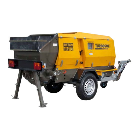
Summary of Contents for Turbosol BETON MASTER
- Page 1 ORIGINAL OPERATION AND MAINTENANCE MANUAL BETON MASTER IS19/07 561270 Serial number Year...
-
Page 3: Table Of Contents
INDEX CE DECLARATION ....................7 CE DECLARATION OF CONFORMITY ..................7 GENERAL INFORMATION ..................9 IMPORTANCE OF MANUAL ......................9 ABBREVIATIONS ..........................9 INFORMATION ON CONSULTING THE MANUAL ..............9 MEANING OF SYMBOLS ......................9 MACHINE OFF..........................10 GENERAL AND CONTACT INFORMATION ................10 TECHNICAL DESCRIPTION .................. 11 NAME OF MACHINE ........................11 DIMENSIONS OF MACHINE .......................12 TECHNICAL DATA ........................12... - Page 4 OPERATING PRINCIPLE ......................29 PUMPABLE SLURRIES ......................29 CHECKS BEFORE START-UP ....................30 CONTROLS ..........................32 STARTING THE MACHINE ......................34 CLEANING THE MACHINE AFTER A WORK SESSION ............35 7.6.1 Washing the piping ........................36 FLUSHING WITH WATER ......................36 FLUSHING WITH COMPRESSED AIR ..................37 CLEANING BY REVERSE PUMPING ..................37 IMPORTANT WARNING ......................37 MAINTENANCE ......................
- Page 5 11.2 WARRANTY ..........................57...
-
Page 7: Ce Declaration
CE DECLARATION CE DECLARATION CE DECLARATION OF CONFORMITY An original copy of the CE Declaration of Conformity is supplied separately from the manual. 7/58 561270 – IS19/07 - EN... - Page 8 CE DECLARATION 8/58 561270 - IS19/07 - EN...
-
Page 9: General Information
GENERAL INFORMATION GENERAL INFORMATION IMPORTANCE OF MANUAL The present Operation and Maintenance Manual has been prepared following the guidelines contained in the relevant European Directives. Its purpose is to provide a simple and full understanding of the subjects dealt with to the persons authorized to operate and perform maintenance on the machine described. -
Page 10: Machine Off
35-REF. 1). GENERAL AND CONTACT INFORMATION The BETON MASTER concrete pump can be supplied with a number of different accessories, therefore not all the parts described in this manual may be actually installed on your machine. The Customer Service department of Turbosol Production S.R.L. will be glad to provide any information you may need. -
Page 11: Technical Description
TECHNICAL DESCRIPTION TECHNICAL DESCRIPTION NAME OF MACHINE CE Marking FIG. 01 The series (1), the machine model (2) and the machine's serial number (3) and the power data are engraved on the plate. Below is the meaning of the used symbols. (1) = Machine series. -
Page 12: Dimensions Of Machine
TECHNICAL DESCRIPTION DIMENSIONS OF MACHINE The following are the machine's overall dimensions and gross weight (in working conditions). BETON MASTER D LENGTH WIDTH HEIGHT WEIGHT* 3335 mm 1420 mm 1600 mm 1560 kg TAB. 02: BETON MASTER D/T LENGTH WIDTH... -
Page 13: Intended Uses
TECHNICAL DESCRIPTION INTENDED USES The machine has been designed and built for the following use: FIELD OF USE: CONSTRUCTION WORK. INTENDED USE: PUMPING SHOTCRETE AND CONCRETE MATERIALS USED - Concrete with maximum particle size 25 mm if aggregates obtained by crushing; maximum particle size 30 mm in case of spheroidal aggregates. - Page 14 TECHNICAL DESCRIPTION 14/58 561270 - IS19/07 - EN...
-
Page 15: Transportation And Handling
TRANSPORTATION AND HANDLING TRANSPORTATION AND HANDLING TRANSPORTING THE MACHINE AS A VEHICLE TRAILER Only machines with a frame equipped with vehicle towing gear are allowed to circulate on public roads. Always respect the rules of the road when towing the machine. The machine cannot be used for carrying loads of any kind, not even the removable accessories used for its operation (pipes, fittings, gaskets, etc.). - Page 16 When unhitching on a slope, block the machine using the parking brake and the chocks so that it won't move after unhitching. BETON MASTER can also be carried on motor vehicles; loading, securing and transporting the machine on a motor vehicle should always be done in compliance with the rules of the road. See paragraph 4.2, LIFTING, for information on using lifting apparatus to load BETON MASTER on a vehicle.
-
Page 17: Lifting
LIFTING BETON MASTER is provided with four lifting points and supplied with a lifting beam (FIG. 10). - Fasten the ropes to the lifting beam (FIG. 10-REF. 1) and to the four lifting points, attaching the shorter ropes to the hooks shown in FIG. - Page 18 TRANSPORTATION AND HANDLING 18/58 561270 - IS19/07 - EN...
-
Page 19: Installation
FIG.11 FIG.12 - Place BETON MASTER at the point of the worksite where you can use the pipes and hoses to their full extension. - Brake the machine and block the wheels using the chocks supplied. - Make sure the machine is resting on its side support legs and then raise the wheel. -
Page 20: Piping Layout
INSTALLATION 5.2.1 Piping layout BETON MASTER can pump slurries horizontally, upwards or downwards. Here below are a few general rules that should be followed when setting up the various layouts. FIG.13 FIG.14 HORIZONTAL PUMPING In case of horizontal pumping simply lay out the pipe in the desired layout and connect it to the first section described above. -
Page 21: Concrete Piping Fittings
INSTALLATION CONCRETE PIPING FITTINGS Make sure the fittings are clean and in good order at all times. Check the rubber gasket (FIG.17-REF.1) is present and fully fasten the levers (FIG.17-REF.2) when connecting the piping segments. Lock coupling with safety pin to avoid inadvertent openings (FIG.17A-RIF.3). FIG.17 FIG.17A CONNECTIONS... -
Page 22: Remote Control
INSTALLATION FIG.18 FIG.19 - Connect the slurry delivery hose (FIG. 20-REF. 1) to the shotcrete nozzle and the air delivery hose (FIG. 20-REF. 2) to the nozzle and to the auxiliary compressor. - Connect the additive delivery hose to the spraygun (additive dosing kit is optional). FIG.20 Accelerating additives are harmful. -
Page 23: Connecting The Radio Control (Optional)
INSTALLATION FIG. 21 5.4.3 Connecting the radio control (optional) - Connect the plug (FIG. 22-REF. 1) to the connector socket (FIG. 22-REF. 2). - Press the button (FIG. 22-REF. 3) to switch the remote control on and off. - Press the button (FIG. 22-REF. 4) to start pumping. Press the button again to stop pumping. - To reverse pumping (i.e., sucking the mix from the pipe on the hopper), make sure the button (FIG. - Page 24 INSTALLATION 24/58 561270 - IS19/07 - EN...
-
Page 25: Safety
SAFETY SAFETY SAFETY DEVICES MUSHROOM-SHAPED EMERGENCY BUTTON Located on the control column it stops power supply in case of an emergency. PROTECTION GRID IN UPPER HOPPER The grid preventing access to the oversized aggregate and contact with the S valve, is found inside the upper hopper. GRID OPENING SENSOR Sensor interrupting pumping when the grid opens with machine running. -
Page 26: Safety Signs
SAFETY SAFETY SIGNS The safety signs are adhesive labels affixed outside and inside the machine. The safety signs must be kept clean and clearly visible at all times. E' obbligatorio sostituire la segnaletica di sicurezza deteriorata, facendone richiesta al fabbricante. assolutamente vietato rimuovere... - Page 27 SAFETY PARTS UNDER PRESSURE:: Inspect the piping and make sure there are no signs of damage. Make sure all the quick-release couplings and pipe joints are tight. Make sure the vertical piping fasteners are securely fastened. Do not open pipe fittings when the pipe is under pressure. HOT PARTS: Do not open the casing while the machine is running.
- Page 28 SAFETY 28/58 561270 - IS19/07 - EN...
-
Page 29: Use And Operation
OPERATING PRINCIPLE At the core of the BETON MASTER is the pumping assembly, consisting of: the lower hopper (FIG. 29-REF. 1), which containes the S-valve (FIG. 29-REF. 2), and the mixer (FIG. 29-REF. 3). Behind the hopper are two oil-hydraulic jacks (FIG. 29- REF. -
Page 30: Checks Before Start-Up
USE AND OPERATION CHECKS BEFORE START-UP The oil level and the coolant level should be checked with the machine switched off. - Check the level of the liquid inside the expansion vessel (FIG. 30-REF. 1) above the heat exchanger. To top up the liquid unscrew the cover (FIG. - Page 31 USE AND OPERATION FIG.32 FIG.33 - Top up the diesel fuel tank (FIG. 33) at the end of every work session to avoid the forming of condensate inside the tank when the machine cools down. - Make sure there is water inside the tank (FIG. 34-REF. 1). FIG.
-
Page 32: Controls
USE AND OPERATION CONTROLS MASTER START ON/OFF FIG. 35 FIG.36 32/58 561270 - IS19/07 - EN... - Page 33 USE AND OPERATION FIG. REF. DESCRIPTION Ignition key Activation button Hour meter Pumping and sucking start/stop Mixer Start/stop/Reverse Vibrating screen activation/stop Local/remote control selector switch High pressure washer S-valve manual control and pumping cylinders S-valve manual control and pumping cylinders Emergency stop button Flow rate regulator Accelerator...
-
Page 34: Starting The Machine
USE AND OPERATION STARTING THE MACHINE - Package an adequate amount of grout (water and cement): • pumping up to 20 m - 40/50 litres • pumping beyond 20 m - 50/80 litres - Check the emergency button (FIG.36-REF.1) is not engaged. - Insert the ignition key and turn it to ON The pre-heating phase starts automatically, once the key has been turned. -
Page 35: Cleaning The Machine After A Work Session
USE AND OPERATION CLEANING THE MACHINE AFTER A WORK SESSION The following operations should be carried out only by specifically trained personnel. In particular, before breaking a joint make sure there is no residual pressure inside the piping and that no one is standing nearby. -
Page 36: Washing The Piping
USE AND OPERATION Never direct the water jet at people. Wear appropriate protection, in particular for your hands and eyes. Do not direct the water jet at electric or hydraulic components. FIG.38 7.6.1 Washing the piping The pipes and hoses can be washed in three different ways: 1) by flushing with water under pressure 2) by flushing with compressed air 3) by reverse pumping (vertical piping only) -
Page 37: Flushing With Compressed Air
USE AND OPERATION FLUSHING WITH COMPRESSED AIR - Connect the basket (FIG. 40-REF. 1) designed to catch the sponge to the end of the hose using a Victaulic coupling complete with rubber gasket. - At the other end, introduce an adequately-sized pipe sponge (FIG. 40-REF. 2) soaked in water, connect the flushing cap supplied (FIG. - Page 38 USE AND OPERATION a metallic sound means the pipe is clear, while a dull sound indicates a clogged pipe. - Detach the piping between the clogging and the front delivery flange (FIG. 55-REF. 1). - Disconnect the steel pipe downstream from the clogging. Once you have separated it from the line, hold the clogged section vertically and clean it out.
-
Page 39: Maintenance
MAINTENANCE MAINTENANCE MAINTENANCE TO BE CARRIED OUT BY OPERATOR The following are the basic instructions for performing proper maintenance on the machine. More detailed information can be found in the diesel engine operation and maintenance manual (supplied), which operators are required to read and understand (along with the present manual) before using the machine. CHECKING THE LUBRICATION WATER LEVEL - Open the discharge lever (FIG. -
Page 40: Checking The Hydraulic Oil Level
MAINTENANCE Top up the diesel fuel tank at the end of every work session to avoid the forming of condensate inside the tank when the machine cools down. CHECKING THE HYDRAULIC OIL LEVEL Check the level of the oil in the hydraulic oil tank through the inspection window (FIG. 45-REF. 1). If the oil level does not remain constant there may be a leak that must be found and stopped;... - Page 41 MAINTENANCE FIG.47 - Empty the water tank. - Start the machine, and with the engine idling, turn the handwheel (r1) to set the flow of the hydraulic pump at minimum. - Start reverse pumping. - Watch the hopper and when one of the pistons reaches the end of its stroke lift the safety grid to stop the pumping. - Stop the machine.
- Page 42 MAINTENANCE FIG.50 FIG.51 - Screw the M20 threaded rod (FIG. 51-REF. 1) onto the piston head, screw on the nut (FIG. 51-REF. 2) and pull out the piston. - Remove the piston with the guide ring (FIG. 52). FIG.52 FIG.53 To install a new piston proceed as follows: - Slide the guide spacer (FIG.
-
Page 43: Adjusting The S-Valve
MAINTENANCE FIG.54 FIG.55 - Apply more Vaseline. - Push the piston completely into the guide ring, screw on the threaded rod M16 (FIG. 55-REF. 1) and the threaded nut (FIG. 55-REF. 2). - To make the piston reach the piston rod (FIG. 56/57-REF. 1) apply the spacers and keep tightening the nut. FIG.56 FIG.57 - Unscrew and remove the nut, remove the M16 threaded rod, the spacers, the guide ring and the guide ring spacer. -
Page 44: Replacing The Wear Disc, The Wear Plate And The S-Valve
MAINTENANCE - Start the machine and, with the engine running idle, make sure the S-valve switches regularly. FIG.58 REPLACING THE WEAR DISC, THE WEAR PLATE AND THE S-VALVE The following steps must be carried out with the machine switched off. - Remove the upper hopper by unscrewing its four fastening screws. - Page 45 MAINTENANCE - Remove the 5 fastening screws (FIG. 61-REF. 1) and take out the wear plate. - Apply two new O-rings (FIG. 61-REF. 2) lubricating them with grease (the grease keeps the rings in place). Do not apply too much grease because it creates thickness. - Install and fasten the wear plate.
-
Page 46: Changing The First Oil Filter
MAINTENANCE FIG.63 - Reinstall the delivery flange and the grease fitting. - Reinstall the upper hopper and the safety grid. - Start the machine and make sure the S-valve switches regularly. CHANGING THE FIRST OIL FILTER The following steps must be carried out with the machine switched off and the oil cooled down. The hydraulic oil tank is provided with two filters. - Page 47 MAINTENANCE FIG.65 - Open the valve (FIG. 66-REF. 1) beneath the oil tank to drain the tank, placing an adequately sized container below it to collect the oil. - Disconnect the hydraulic oil pipe (FIG. 64-REF. 3). - Unscrew and replace the internal filters (FIG. 66-REF. 2/3) and close the tank after inspecting the conditions of the gasket (replace if necessary).
-
Page 48: To Be Carried By Qualified Personnel
- Check the valve clearance and adjust if necessary. - Check the engine mountings and tighten if necessary. - Check the tightness of the pumping sensors, the safety sensors and the BETON MASTER operation sensors (diesel fuel level, hydraulic oil temperature, coolant temperature). -
Page 49: Maintenance To Be Performed Every Six Months Or Every 500 Hours
MAINTENANCE - Replace the fuel filter. - Replace the oil filter on the additive metering pump. - Replace the engine air filter cartridges. - Check the sleeves in the cooling circuit and replace any worn sleeves. - Check the density of the coolant. 8.7.4 Maintenance to be performed every six months or every 500 hours - Check the glow plugs. - Page 50 MAINTENANCE All maintenance work should be carried out by trained personnel in authorized workshops or service centres. 50/58 561270 - IS19/07 - EN...
-
Page 51: Scrapping
SCRAPPING SCRAPPING GENERAL INFORMATION Follow the local regulations at the time of scrapping the machine. Separate the machine parts according to the type of material (plastic, rubber, iron, etc.). The oil, the coolant and the storage cell must be handed over to authorized firms specializing in the disposal of polluting products. - Page 52 SCRAPPING 52/58 561270 - IS19/07 - EN...
-
Page 53: Troubleshooting
- act on the m1 lever bringing it to position 2, holding it in position for a few seconds, - carry out previous operation for the m2 lever also, - re-start pumping. Immediately inform Turbosol service of the problem. 53/58 561270 - IS19/07 - EN... -
Page 54: Operator's Intervention
TROUBLESHOOTING 10.3 OPERATOR'S INTERVENTION PROBLEMS CAUSES SOLUTIONS • Check the battery disconnector is active No electric power supply. THE CONTROL BOARD DOES NOT • Check the battery charge and main fuse state. SWITCH-ON Fault in control board • Contact the authorised assistance. •... - Page 55 TROUBLESHOOTING 55/58 561270 - IS19/07 - EN...
- Page 56 TROUBLESHOOTING 56/58 561270 - IS19/07 - EN...
-
Page 57: Responsibility Of The Operator
WARRANTY The machinery manufactured by Turbosol Produzione S.R.L. is guaranteed for a period of twelve (12) months or one thousand (1,000) hours of operation - whichever comes first - from the date said machinery is delivered to the end consumer, and in any event not more than eighteen (18) months from its shipment. - Page 58 RESPONSIBILITY OF THE OPERATOR 58/58 561270 - IS19/07 - EN...
Need help?
Do you have a question about the BETON MASTER and is the answer not in the manual?
Questions and answers