
Related Manuals for Turbosol PRO H CL


Summary of Contents for Turbosol PRO H CL
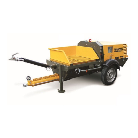
- Page 1 ENGLISH INSTRUCTION FOR USE AND MAINTENANCE CT. 200.411 ITALIANO COMPREHENSIVE CATALOGUE & SPARE PARTS Serial number PUMPING SYSTEM FOR THE BUILDING INDUSTRY...
-
Page 2: Table Of Contents
CONTENTS USE AND MAINTENANCE 1. - General information 1.1 - Introduction 1.2 - General information 2. - Description of the machine 2.1 - Type of machine Manufacturer’s registration plate Position of the manufacturer’s plate Position of the serial number of the machine On road towing 2.2 - Description of the machine 2.3 - Description of control panel... - Page 3 Written authorization from Turbosol Produzione SpA must be obtained for any and all reprinting or reproduction, even in part, of the information contained in this booklet.
- Page 4 SYMBOL KEY DESCRIPTION It is compulsory to read this It is compulsory to read this maintenance booklet for what maintenance booklet prior to regards ordinary and general operating the machine maintenance. Danger: electrical shock hazard. CAUTION ! A - The canopy must remain closed when working with E - When towing connect the safety cable and the tail the machine.
-
Page 5: General Information
1 - GENERAL INFORMATION 1.1 - INTRODUCTION 1.2 -GENERAL INFORMATION The machine for self levelling materials PRO H CL can Turbosol Machinery be supplied with a number of different accessories. As a This machinery is the product of our lengthy experience result, some of the components and parts described in this and continuous development. -
Page 6: Description Of The Machine
The following is the meaning of the letters and numbers used: (A) = Tipo di macchina: PRO H CL PRO H CL = Machine for self levelling materials. Position of the serial number of the machine The serial number of the machine (2) is punched on the chassis and also on the manufacturer’s plate... -
Page 7: Description Of The Machine
2.2 - DESCRIPTION OF THE MACHINE Standard equipment: Accessories upon request • Self-bearing chassis frame and canopy. Vibrator for sieve. • 200 l hopper with built-in agitator. High pressure water pump. • Sieve with mesh of 15 mm. Radio control with 5 functions. •... -
Page 8: Description Of Control Panel
2.3 - DESCRIPTION OF CONTROL PANEL Control panel Some indications are given below regarding the controls and indicator lights to be found on the control panel. • The following may appear on the display (a): The indicator light (STOP) shows that the hopper safety - the time of machine operation given in hours grid is open or activation of the pneumatic remote control. - Page 9 DESCRIPTION OF ALARM INDICATOR LIGHTS • Maintenance work The machine is programmed to request periodic Battery charge alarm maintenance: the fi rst servicing is scheduled after 50 hours It is possible to work with the machine for up to of operation while subsequent maintenance is scheduled 180 minutes (approx.
-
Page 10: Size Of The Machine
2.4 - SIZE OF THE MACHINE Here the size and gross weight of the equipment (ready to work). VERSION PRO H CL LENGHT WIDTH HEIGHT WEIGHT 3.397 mm 1.410 mm 1.150 mm 690 kg 2.5 - TECHNICAL DATA Power of diesel engine... -
Page 11: Transport
3 - TRANSPORT 3.1 - WHEN TOWING ON ROAD 3.2 - HOISTING Before towing the machine: Hook the cable on the lifting eye placed above the • Check that the canopy is properly locked; chassis. • Check the tow bar, the hook on the towing vehicle and the towing hook;... -
Page 12: Use Of The Machine
4 - USE OF THE MACHINE 4.1 - WORKING PRINCIPLE 4.2 - PUMPABLE MATERIALS The PRO H CL consists basically of an hopper with built-in Applications: agitator which receives the mix and a worm gear pump for The PRO H CL pumps various materials such as: pumping the material. -
Page 13: Preliminary Operations
The machine must be placed at a spot in the building site where you can better use the action radius of the mortar hoses. Use only original hoses and couplings. The couplings must be mounted only by TURBOSOL PRODUZIONE S.p.A: or by authorized companies. Under circumstance... -
Page 14: Coupling Devices
Coupling Devices Connections Check to be certain that the coupling devices are clean Connect the material hose (15) to the worm pump. and in good working order. • Cam-locks When connecting the hoses together make sure that the rubber gaskets are mounted (14). Lock the levers completely. - Page 15 Cable remote control (standard) Radioremote control (optional) In order to use the cable remote control is necessary to If the machine is fi xed with radioremote control you should fi x it to the connector (19) placed on the right side of the act as follows: •...
-
Page 16: Operation
4.4 - OPERATION • Gasoil level RELIMINARY CONTROLS Carry out the following controls: It is a good habit to refi ll the gasoil tank at the end of the shift in order to prevent condensation inside the tank. • Engine oil level The level must be almost at the maximum. -
Page 17: Pump Setting
• Pump setting (indicative) ORRECT PRESSURE VALUES If you have installed a new pump, and in any before PUMP HOSE LENGHT UP TO starting a new shift it is advisable to check the setting of 40 m 50 m 60 m the pump by carrying out the following procedure: 60.12* 8 bar... -
Page 18: Starting Standard Machines
Starting machines • The Access Code Fill-up the hopper with water in order to avoid that the A request for the access code appears on the display as screw turns dry. follows. 0000 Check that the emergency (34) button is not on. Access Code The four-digit access code, which is given to the user when the machine is delivered, must be specifi... - Page 19 The following indications appear on the display: • Press the START (c2) button and keep it pressed until the Vbat: 12.5 engine has started. Glow plugs heating In any case do not keep the button (c2) pressed for longer The battery voltage value is shown at the top, so that its than 15 seconds.
-
Page 20: Transporting The Mix
Transporting the mix Empty the water left in the hopper by opening the plug at the bottom of the hopper. Use Nitrile gloves to protect yourself against cuts and abrasions. Preferably use models certifi ed CE 940072. Use goggles, possibly with polycarbonate break- proof lenses, to protect your eyes. - Page 21 Vibrating sieve Start the electric vibrator (optional) of the vibrating sieve by pressing the relative button (h1) ON/OFF. If the indicator light (h2) is on, this means that the electric vibrator is in operation. The vibrating sieve cannot be operated continuously but for just one and a half minutes at the most every fi...
- Page 22 The remote control of the machine is done by means of a Electric remote control (standard) cable remote control (11) with 4 functions or radio remote To operate with the electric remote control, it must be control (12) with 5 functions. (optional). connected to the connector socket (19) located on the right side of the machine.
- Page 23 Radioremote control (optional) If the machine is fi xed with radioremote control you should act as follows: • on the button (23) in order to start the mortar pump, • on the button (24) in order to stop it, • on the buttons “–” (25) and “+” (26) in order to change the output, •...
-
Page 24: Cleaning At The End Of The Work
4.5 - CLEANING AT THE END OF THE WORK Pump the last mix and once you start seeing the agitator Disconnect the delivery hopper and clean it properly. shaft stop the pump. Disconnect the mortar hose from the mortar pump and insert a cleaning sponge ball at the beginning of it. -
Page 25: High Pressure Water Pump
The machine can be fi tted with a high pressure water Before stopping the machine it is necessary to: pump (optional). By using it for washing the machine: • Shut-down the mortar pump (e1) by pressing ON/OFF • Connect a water hose button. -
Page 26: Changing The Pumping Group
4.6 - CHANGING THE PUMPING GROUP In order to replace the pump group proceed as follows: Take the stator / rotor assembly and put it in a vice, block the stator and Before performing this operation stop the with a 12 mm rod of suitable pump and than shut-down the engine. - Page 27 If the assembly is impossible with this procedure, take the group with the worm partially inserted and bang it on the fl oor several times. Check that the distance between the worm bolt orifi ce and the rotor is of at least 85 mm. 85 mm •...
-
Page 28: Maintenance Of The Machine
5 - MAINTENANCE OF THE MACHINE 5.1 - OPERATIONS FOR WHICH THE OPERATOR IS RESPONSIBLE The essential data for a correct maintenance of • Check engine air fi lter the machine are listed hereunder. More detailed This fi lter is composed of two cartridges (1st and 2nd indications regarding the maintenance of the diesel engine stage). - Page 29 At the end of the work • Grease the agitator (46) by using the grease gun delivered. For a successful result of this operation the grease must come out from the seals. In you forget to run this operation the seals and the support will deteriorate quickly (within a few days).
-
Page 30: Maintenance To Be Performed By Authorized Personnel
5.2 - MAINTENANCE TO BE PERFORMED BY AUTHORIZED PERSONNEL SERVICING MAINTENANCE OPERATIONS AFTER 50 HOURS The machine is programmed to indicate when periodic maintenance is required: After 50 hours you must run a fi rst control on the - the fi rst work is scheduled after 50 hours of operation, machine. - Page 31 Operations to be carried out MONTHLY or at EVERY Operations to be carried out EVERY 2 MONTHS or at 125 HOURS EVERY 250 HOURS. • Change the engine oil. • Change the air fi lter. • Change the gasoil fi lter. •...
-
Page 32: Trouble Shooting
6 - TROUBLE SHOOTING 6.1 - FAULTY MIX A wrong mix or a very long pause can cause a blockage Find out where the material hose line is plugged; in this inside the material hose; no mortar comes out from the point the hose is hard and rigid. -
Page 33: Operator Intervention
6.2 - OPERATOR INTERVENTION ROBLEMS AUSES EMEDIES Stator clamp too tight. • Allentare strettore. Mortar pump blocked Working pressure too high. • Modifi care l’impasto o ridurre la (oil pressure gauge shows 210 lunghezza delle tubazioni o utilizzare bar) tubazioni di diametro maggiore. Hose plugged. -
Page 34: Responsibility Of The Operator
7 - RESPONSABILITY OF THE OPERATOR of the machinery is responsible PERSON IN CHARGE for assuring that whoever operates such machinery is well aware of the instructions contained in this use and maintenance manual, and in particular that said operator has received special training in the proper execution of those operations marked in the manual by the following symbol:... - Page 35 S PA R E PA RT S G E N E R A L C ATA LOGUE...
- Page 36 TABLE 1 - MACHINE BODY N-01...
- Page 37 N° REF Q.TY DESCRIPTION 221.444 Machine body 225.863 Dividing pane 225.827 Support of the direction control block 225.842 Screwed crutch DX 225.843 Screwed crutch SX 227.283 Crutch pin 251.313 Stopper 247.134 Gasket 266.481 Support 266.480 Stop wheels 216.644 Connection 266.283 Galvanized hinge 263.392 Handle...
- Page 38 TABLE 2 - TRANSMISSION - PUMP 60.12 N-02...
- Page 39 N° REF Q.TY DESCRIPTION 212.879 Motor for cylindrical shaft 241.386 Hopper coupling fl ange 263.104 Seal ring 55 x 72 x 10 248.065 Seal gasket 245.106 Galvanized gasket stopper 251.294 Hopper agitator hub 540.090 Screw TCEI M8 x 30 266.289 Agitator screw TE M18 x 100 542.024 Self-locking nut M18...
- Page 40 TABLE 4 - OLEO-DYNAMIC PLANT N-04...
- Page 41 N° REF Q.TY DESCRIPTION 261.079 Nipples oleo 1/2” 261.297 Oleo T coupling MMF 1/2” revolving 215.056 Oleo-dynamic duct F90° - F90° 1/2” 261.582 Oleo extension MF 1/2” x 40 261.093 Nipples oleo 3/4” - 1/2” 215.013 Oleo-dynamic duct F90° - F90° 1/2” 215.084 Oleo-dynamic duct F90°...
- Page 42 TABLE 5 - VIBRATING SIEVE N-05...
- Page 43 N° REF Q.TY DESCRIPTION 229.132 Vibrating sieve 229.133 Frame with sieve 238.000 Shock absorber 542.024 Self-locking nut 542.009 Nut Ø 18 238.060 Shock absorber 241.382 Pin for sieve 261.241 Greaser hydraulic 238.022 Shock absorber Ø 40 x 40 206.249 Motor-vibrator KIT 211.266 Moto-vibrator 621.016...
- Page 44 TABLE 6 - COMPONENTS N-06...
- Page 45 N° REF Q.TY DESCRIPTION 215.177 Pump with variable output 215.184 Filter 216.539 Diesel engine 274.186 Filter gasoil --- . --- Filter 266.455 Flexible pipe 266.456 Fiber of glass 227.538 Motor support 227.536 Motor support 227.537 Motor support 265.007 Damper 241.358 Fan spacer 263.378 214.282...
- Page 46 TABLE 13 - ELECTRIC BOARD N-07...
- Page 47 N° REF Q.TY DESCRIPTION 211.493 - Electric board PRO H 216.551 Control panel for diesel engine 274.402 Block of lighting...
- Page 48 TABLE 8 - ON-ROAD TOWING N-08...
- Page 49 N° REF Q.TY DESCRIPTION 266.419 Axle 750 kg 216.376 Complete wheel 227.480 Support for right mudguard 227.481 Support for left mudguard sx 237.116 Right rounf mudguard - ABS black 237.124 Left round mudguard - ABS black 211.292 Kit light bar 214.470 Light 5 fonctions + right rear refl...
- Page 50 TABLE 9 - ACCESSORY BOX code 201.114 N-09 Ø 60...
- Page 51 N° REF Q.TY DESCRIPTION 201.114 - Accessory box for self-levelling fl oors 251.193 Delivery hose DN50 for shotcrete 216.195 Setting group DN50 266.201 Plug for setting DN50 261.110 Nipples 212.054 Ball cock FF 3/4” 237.017 Washing sponge Ø 60 543.018 268.018 Screwdriver 268.008...
- Page 53 WI R I N G D I A G R A M S...
- Page 54 PUMPING SYSTEM FOR THE BUILDING INDUSTRY TURBOSOL PRODUZIONE Via Volta, 1 31030 Pero di Breda (TV) - Italia Tel. ++39 0422 90 251 Fax ++39 0422 904 408 E-mail: info@turbosol.it www.turbosol.it...
Need help?
Do you have a question about the PRO H CL and is the answer not in the manual?
Questions and answers