
Subscribe to Our Youtube Channel
Related Manuals for Exerpeutic 275SL


Summary of Contents for Exerpeutic 275SL
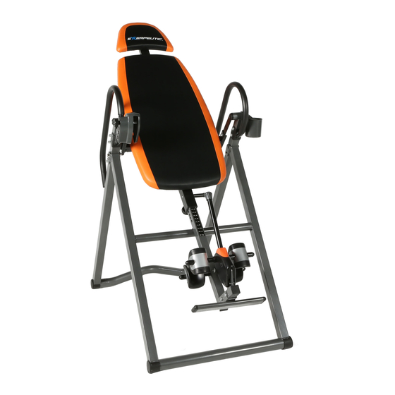
- Page 1 EXERPEUTIC 275SL Inversion Table with ‘SURELOCK’ Safety Ratchet Ankle Locking System The specifications of this product may vary from this photo and are subject to change without notice. OWNER’S MANUAL 4530.2-121517...
- Page 2 PLEASE DO NOT RETURN THIS PRODUCT TO THE STORE. STOP. Contact customer service if you have any questions regarding assembly or proper operation of the machine. Email us at: Service@paradigmhw.com Or call us at: 1-844-641-7921 Hours: 8:00 am to 5:00 pm (PST) Daily...
-
Page 3: Table Of Contents
TABLE OF CONTENT SERVICE---------------------------------------------------------------------- IMPORTANT SAFETY GUIDELINES---------------------------------- LABEL PLACEMENT------------------------------------------------------- 5 OVERVIEW DRAWING---------------------------------------------------- 6 PARTS LIST------------------------------------------------------------------- 7 HARDWARE & PARTS PACK-------------------------------------------- 9 ASSEMBLY-------------------------------------------------------------------- 10 OPERATION & ADJUSTMENTS---------------------------------------- 21 STORAGE--------------------------------------------------------------------- 28 WARRANTY------------------------------------------------------------------- 29 PARTS REQUEST FORM------------------------------------------------- 30... -
Page 4: Service
SERVICE IMPORTANT: FOR NORTH AMERICA ONLY For damaged or defective product, questions, replacement parts or any other service support, please contact our customer service department by the below methods: For The Best Service, please Email: service@paradigmhw.com Response Time: 1-2 Business Days Emailing us with the information above will be the best method to receive a response during peak business hours Website:... -
Page 5: Important Safety Guidelines
IMPORTANT SAFETY GUIDELINES Read all instructions before using the Inversion Table. When using an Inversion table, basic precautions should always be followed, including the following: WARNING - To reduce the risk of injury to persons: Make sure your equipment is correctly assembled before you use it. Be sure all screws, nuts, and bolts are tightened prior to use. - Page 6 IMPORTANT SAFETY GUIDELINES WARNING: - Risk of Personal Injury - Do not attempt to service the unit yourself. Discontinue use and contact customer service. WARNING: - To Reduce The Risk Of Personal Injury - Read And Understand All The Instructions Before Using The Inversion Table. Do not use this equipment if you have any of the following conditions or ailments: •...
-
Page 7: Label Placement
LABEL PLACEMENT... -
Page 8: Overview Drawing
OVERVIEW DRAWING... -
Page 9: Parts List
PARTS LIST Description Description Backrest 30 Foot Bar Oval End Cap Backrest Frame 31 Foot Cap Adjustable Boom 32 Flat Washer Ø13xØ6.5x1.5 Foot Bar 33 Hex Bolt M6x40mm Rear Rod 34 Square End Cap 6L Left Handlebar 35 Upper Bed Frame End Cap 6R Right Handlebar 36 Rubber Pad Steel Heel Holder Bracket... - Page 10 PARTS LIST Description Description 60 Spring 65 Latch Self-Tapping Phillips Screw 66 Adjustable Knob ST3.5x13 64 Plastic Spacer 67 Head Cushion...
-
Page 11: Hardware & Parts Pack
HARDWARE & PARTS PACK... -
Page 12: Assembly
ASSEMBLY This product weighs more than 44lbs/20kgs and should be assembled and moved by two or more people. Step 1 Setting Up the Frame: Stand the frame up by pulling the Front and Rear Frames (9, 8) as far apart from each other possible. - Page 13 ASSEMBLY Tools: 10, 13, 17mm Wrench 1PC 6mm Allen Wrench 1PC Step 2 Installing the Left Handlebar: 2A. Install the Left Handlebar (6L) onto the Rear Frame (8) with two Socket Hex Bolts (20), four Flat Washers (19), two Cap Nuts (24), one Socket Hex Bolt (15) and one Flat Washer (16). Tighten the hardware using the 10, 13, 17mm Wrench and the 6mm Allen Wrench provided.
- Page 14 ASSEMBLY Fig. Step 3 Hardware Removal: 3A. Remove the Plastic Spacer (17), Plastic Round End Cap (18), and Socket Hex Bolt (28) from the Rear Frame (8) with the 6mm Allen Wrench provided. See Fig. A. Keep the Socket Hex Bolt (28) for the Cup Holder (23) installation.
- Page 15 ASSEMBLY Tools: 10, 13,17mm Wrench 1PC 6mm Allen Wrench 1PC Step 4 Installing the Backrest: Warning: The Socket Head Bolts (28) should be installed from the inside as shown in the illustration above. 4A. Attach the Backrest (1) onto the Left and Right Pivot Arm (10L, 10R) by aligning the holes of the Left and Right Pivot Arm (10L, 10R) with the brackets of the Backrest (1).
- Page 16 ASSEMBLY Tools: 10, 13,17mm Wrench 1PC 6mm Allen Wrench 1PC Step 5 Installing the Right Handlebar: 5A. Install the Right Handlebar (6R) onto the right side of the Rear Frame (8) with two Socket Hex Bolts (20), four Flat Washers (19), and two Cap Nuts (24). NOTE: The Cap Nuts (24) should be installed on the outward facing side of the frame.
- Page 17 ASSEMBLY Fig. C Step 6 Installing the Right Handlebar Cover: 6A. Attach the Right Handlebar Cover (53R) onto the tab on the Rear Frame (8) with one Self-Tapping Phillips Screw (54). Tighten the screw with the Multi-Hex Tool with Phillips Screwdriver provided.
- Page 18 ASSEMBLY Fig. E Correct Incorrect Step 7 Installing the Locking Pin: 7A. With the backrest in the upright position, insert the Adjustable Knob (66) into one of the holes on the Right Handlebar (6R). Turn the Adjustable Knob (66) clockwise to tighten it. WARNING: Make sure the Adjustable Knob (66) is fully inserted into the Right Handlebar (6R) before using the inversion table.
- Page 19 ASSEMBLY Fig. F Tools: 10, 13,17mm Wrench 1PC 6mm Allen Wrench 1PC Step 8 Installing the Foot Bar: 8A. Install the Foot Bar (4) onto the Adjustable Boom (3) with two Socket Hex Bolts (20), four Flat Washers (19) and two Nylon Nuts (42). Tighten the hardware with the 6mm Allen wrench and 10, 13, 17 mm Wrench provided.
- Page 20 ASSEMBLY Fig. G Tools: 10, 13,17mm Wrench 1PC Multi-Hex Tool with Phillips Screwdriver 1PC Step 9 Installing the Rear Rod & Heel Holders: 9A. Slide the Rear Rod (5) through the Adjustable Boom (3) with the slots facing forward. Slide the Steel Heel Holder Brackets (7) and Rear Rubber Heel Holders (14) onto both ends of the Rear Rod (5).
- Page 21 ASSEMBLY Fig. H Step 10 Installing the Front Rod & Heel Holders: 10A. Slide the Front Rod (13) through the Plastic Covers (46L, 46R) with the slots facing towards the Adjustable Boom (3). Slide the Steel Heel Holder Brackets (7) and Rear Rubber Heel Holders (14) onto both ends of the Front Rod (13).
- Page 22 ASSEMBLY Step 11 Installing Adjustable Boom to the Bedframe: 11A. Pull out and hold the Spring Knob (41), and slide the Adjustable Boom (3) into the bottom of the Backrest Frame (2). Slide the Adjustable Boom (3) upwards until the desired height is visible just below the bracket on the Backrest Frame (2).
- Page 23 ASSEMBLY Tools: 10, 13, 17mm Wrench 1PC Step 12 Installing the Head Cushion: 12A. Attach the Head Cushion (67) on to the Bed Frame (2) with two Hex Bolts (33) and two Flat Washers (32). Tighten the hardware with the 10, 13,17mm Wrench provided. NOTE: There are 2 installation options for the head rest.
- Page 24 OPERATIONS & ADJUSTMENTS ADJUSTING THE BOOM The Adjustable Boom (3) can be moved to a variety of different positions in order to accommodate the height of the person using the inversion table. To adjust the Adjustable Boom (3): 1. Loosen the Knob (38) and pull out and hold the Spring Knob (41). 2.
-
Page 25: Operation & Adjustments
OPERATION & ADJUSTMENTS GENERAL PRECAUTIONS 1. It is recommended that someone be with you while you are using this inversion table for the first few times. 2. Always wear shoes when using the inversion table. 3. Make sure that the Rubber Heel Holders (14) are secure around your ankles before inverting. 4. - Page 26 OPERATION & ADJUSTMENTS INVERSE PIN CONTROL To control the angle of inversion insert the Adjustable Knob (66) into one of the holes shown below.
- Page 27 OPERATION & ADJUSTMENTS Step 1 Step 2 Step 3 Step 4 ADJUSTING THE FRONT AND REAR RUBBER HEEL HOLDERS 1. Push down on the Button (57) and move the Adjustable Handle (11) away from the Adjustable Boom (3). 2. Step onto the Foot Bar (4) and place your ankles between the Front/Rear Rubber Heel Holders (14).
- Page 28 OPERATION & ADJUSTMENTS BALANCING THE INVERSION TABLE The inversion table is like a very sensitively balanced fulcrum. It responds to very slight changes in weight distribution. So it is very important to make sure that the height is adjusted properly. To do this, mount the inversion table, lock your ankles into the heel holders, and lie back straight with your hands on the handlebars.
- Page 29 OPERATION & ADJUSTMENTS SUGGESTIONS FOR USE 1. Begin slowly: invert only 15~20 degrees to begin with. Stay inverted only as long as you are comfortable. Return upright slowly if you feel uncomfortable. 2. Make gradual changes: increase the angle only if it is comfortable. Increase the angles only a few degrees at a time.
-
Page 30: Storage
STORAGE FOLDING THE INVERSION TABLE For your storage convenience, the inversion table can be folded down to place against a wall, under a bed, or in a storage area. 1. Pull out the Ring Pin (26) from the holes on the Rear Frame (8) and Front Frame (9). Fig. J 2. -
Page 31: Warranty
WARRANTY MANUFACTURER’S LIMITED WARRANTY Paradigm Health & Wellness warrants to the original purchaser that this product is free from defects in material and workmanship when used for the purpose intended, under the conditions that it has been installed and operated in accordance with Paradigm’s Owner’s Manual. -
Page 32: Parts Request Form
PARTS REQUEST FORM Paradigm Health & Wellness, Inc. EMAIL THIS FORM WITH YOUR RECEIPT OF PURCHASE TO Service@paradigmhw.com * NAME:_____________________________________________________________________________________ ADDRESS:__________________________________________________________________________________ CITY:________________________ STATE:_____________ ZIP:_______________________________________ TELEPHONE: (Day)______________________________________________________________________ (Night)_____________________________________________________________________ SERIAL#:___________________________________________________________________________________ MODEL#:___________________________________________________________________________________ PURCHASE DATE:___________________________________________________________________________ PLACE OF PURCHASE:_______________________________________________________________________ PART # DESCRIPTION “YOUR ORDER WILL BE PROCESSED WITHIN 3 BUSINESS DAYS” This form can also be faxed to #: 626-810-2166...
Need help?
Do you have a question about the 275SL and is the answer not in the manual?
Questions and answers