Table of Contents
Advertisement
Quick Links
Advertisement
Table of Contents

Related Manuals for Skyjack ZB2044


Summary of Contents for Skyjack ZB2044
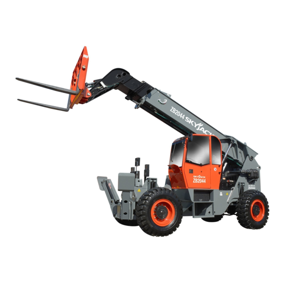
- Page 1 OPERATING MANUAL (ANSI/CSA) TELEHANDLERS MODELS ZB2044 213530ABA July 2018...
- Page 2 We sell worldwide for the brands: Genie, Terex, JLG, MultiQuip, Mikasa, Essick, Whiteman, Mayco, Toro Stone, Diamond Products, Generac Magnum, Airman, Haulotte, Barreto, Power Blanket, Nifty Lift, Atlas Copco, Chicago Pneumatic, Allmand, Miller Curber, Skyjack, Lull, Skytrak, Tsurumi, Husquvarna Target, Stow, Wacker, Sakai, Mi-T-M, Sullair, Basic, Dynapac, MBW, Weber, Bartell, Bennar Newman, Haulotte, Ditch Runner, Menegotti, Morrison, Contec, Buddy, Crown, Edco, Wyco, Bomag, Laymor, EZ Trench, Bil-Jax, F.S.
- Page 3 We sell worldwide for the brands: Genie, Terex, JLG, MultiQuip, Mikasa, Essick, Whiteman, Mayco, Toro Stone, Diamond Products, Generac Magnum, Airman, Haulotte, Barreto, Power Blanket, Nifty Lift, Atlas Copco, Chicago Pneumatic, Allmand, Miller Curber, Skyjack, Lull, Skytrak, Tsurumi, Husquvarna Target, Stow, Wacker, Sakai, Mi-T-M, Sullair, Basic, Dynapac, MBW, Weber, Bartell, Bennar Newman, Haulotte, Ditch Runner, Menegotti, Morrison, Contec, Buddy, Crown, Edco, Wyco, Bomag, Laymor, EZ Trench, Bil-Jax, F.S.
- Page 4 This manual is based on Serial Numbers: ZB 2044 85 800 125 & Above...
- Page 5 The Safety Alert Symbol identifies important safety messages on telehandlers, safety signs This Safety Alert Symbol means attention! in manuals or elsewhere. When you see this symbol, be alert to the possibility of personal Become alert! Your safety is involved. injury or death.
-
Page 6: Table Of Contents
Safety Switches ..........................27 2.8-4 Mirrors ..............................27 2.8-5 Hydraulic ............................28 2.8-6 Cylinders ............................28 2.8-7 Frame ...............................28 2.8-8 Engine Compartment ........................30 2.8-9 Transmission ............................31 2.8-10 Boom ...............................32 2.8-11 Lifting Attachment ..........................32 2.8-12 Grease Points ..........................32 2.8-13 Operator’s Cab ..........................34 ZB2044 Page 4 December 2007... - Page 7 Section 2 - Operation (Continued) Function Tests..............................35 2.9-1 Operator’s Cab Controls .........................35 2.10 Start Operation ..............................44 2.10-1 Starting the Engine ..........................44 2.10-2 Driving the Telehandler ........................45 2.10-3 Driving on Slopes ...........................45 2.10-4 Steering the Telehandler ........................46 2.10-5 Leveling the Telehandler ........................46 2.10-6 Raising or Lowering Boom ......................46 2.10-7...
-
Page 8: Section 1 - About Your Telehandler
Service Policy and Warranty SKYJACK warrants each new ZB series telehandler to be free of defective parts and workmanship for the first 12 months or 2000 hours, whichever occurs first. Any defective part will be replaced or repaired by your local SKYJACK dealer at no charge for parts or labor. -
Page 9: Safety Rules
Some attachments may not be approved for use with certain telehandler models. Use only approved attachments. Any modifications from the original design are strictly forbidden without written permission from Skyjack. ZB2044... -
Page 10: Electrocution Hazard
Section 1 - About Your Telehandler Safety Rules Electrocution Hazard This telehandler is not electrically insulated. Use extreme caution around high-voltage overhead power lines and maintain a Minimum Safe Approach Distance (MSAD) of 10 feet from source of power. Adhere to all federal/ national, state/provincial, or local safety regulations for your own protection. -
Page 11: Safety Precautions
• DO NOT stand on forks. • DO NOT maneuver a load Failure to heed could while moving. This greatly result in death or serious increases the chance of injury. spills and injury. ZB2044 Page 10 December 2007... - Page 12 Section 1 - About Your Telehandler Safety Rules Safety Precautions (Continued) Know and understand all safety precautions before going on to the next section. • DO NOT • DO NOT exceed the maximum safe operating lower the boom slope. unless the area below is clear of personnel and obstruction.
- Page 13 • DRIVE DOWNHILL UNLOADED. provided hand-holds and Without steps only. a load, the back end is the heaviest part of the telehandler. Driving downhill decreases potential for tipover. ZB2044 Page 12 December 2007...
- Page 14 Section 1 - About Your Telehandler Safety Rules Safety Precautions (Continued) Know and understand all safety precautions before going on to the next section. • DRIVE UPHILL • TETHER LOADS that LOADED. When holding swing, keeping load, driving uphill them close to the ground. decreases potential for Provide ample clearance load to slip out.
- Page 15 3 to 5 minutes after a full load operation. Stop engine and remove ignition key to prevent unauthorized use. Block tires. WARNING Always engage park brake and shut off engine before leaving the operator’s cab. ZB2044 Page 14 December 2007...
- Page 16 Section 1 - About Your Telehandler Safety Rules Safety Precautions (Continued) Know and understand all safety precautions before going on to the next section. Jobsite Inspection WARNING • Do not use in hazardous locations (see NFPA 505). Entering and exiting the telehandler •...
-
Page 17: Section 2 - Operation
Section 2 - Operation 2.0 Operation 2.1-2 Operator’s Responsibility for Maintenance This section provides the necessary information needed to operate the telehandler. It is important that the user reads and understands this section before operating WARNING the telehandler. Maintenance must be performed by trained and competent personnel who General are familiar with mechanical procedures. -
Page 18: Major Components
Boom Angle Indicator Attachment Tilt Cylinders Boom Lift Cylinder Engine Air Intake Frame Level Cylinders Fork Carriage Attachment Rear Axle Rear Axle Outriggers Front Axle Operator’s Lock Cylinder and Tire and Tire ZB2044 ZB2044 Telehandler Telehandler ZB2044 Page 18 December 2007... -
Page 19: Major Assemblies
• Maximum capacity boom assembly. The parking brake is a pinion-mounted • Maximum lift height disc brake on the front axle. ZB2044 model is equipped • Maximum machine weight without attachment with a dual service brake system. • Original supplied attachments •... -
Page 20: Component Identification
The operator’s seat is equipped with a seat belt. Use model of telehandler must remain this seat belt at all times when operating the telehandler. with the telehandler and should be stored in this box. ZB2044 Page 20 December 2007... -
Page 21: Operator's Cab Controls
Section 2 - Operation Component Identification 2.5-3 Operator’s Cab Controls Level Indicator - This level indicator allows Boom/Attachment Joystick - This dual-axis the operator to determine the left to right level lever controls the boom raise/lower and extend/ condition of the telehandler. retract functions. - Page 22 “ ” on rocker switch Capacity Charts - This set of charts indicates will operate a left-in function. operating limits specific to a telehandler model and attachments. Refer to Section 2.12. ZB2044 Page 22 December 2007...
- Page 23 Section 2 - Operation Component Identification WAR NING This unit is equipped with rear axle tilt lock, which is energized when red light is lit. Never attempt to level frame when boom is elevated or when red light is lit. 152222AA NOTICE All turbo-engines...
- Page 24 Park telehandler safely and have it Right Arrow Key - Scroll the screen and move the serviced immediately. parameter selection to the right or downward. Enter Key - Select a menu or parameter or hide/ view an active fault code. ZB2044 Page 24 December 2007...
-
Page 25: Component Identification (Special Options)
Section 2 - Operation Component Identification (Special Options) Component Identification NOTE When the ignition is turned off, the reserve (Special Options) oil in the accumulator is released to the The following descriptions are for identification, steer system and may be heard as a explanation and locating purposes only. -
Page 26: Positive Air Shutoff (If Equipped)
After repairs are completed, the operator must perform visual and daily maintenance inspections & function tests again. Scheduled maintenance inspections shall only be performed by a qualified service technician (see Table 2.5). ZB2044 Page 26 December 2007... -
Page 27: Visual & Daily Maintenance Inspections
Section 2 - Operation Visual and Daily Maintenance Inspections Attachment Operator’s Visual & Daily Maintenance 2.8-2 Electrical Maintaining the electrical components is essential to Inspections good performance and service life of the telehandler. Before performing the visual and daily maintenance inspections, ensure that the telehandler is parked on a •... -
Page 28: Hydraulic
• Steer Linkage WARNING Ensure there are no loose or missing parts, steer linkage studs are locked and An over-inflated tire can explode and there is no visible damage. may cause death or serious injury. ZB2044 Page 28 December 2007... - Page 29 Section 2 - Operation Visual and Daily Maintenance Inspections Rear side View Exhaust System Rear Door Standard Batteries • Batteries 5. Replace batteries if damaged or incapable of Proper battery condition is essential to good holding a lasting charge. engine performance and operational safety. Improper fluid levels or damaged cables and WARNING connections can result in engine component...
-
Page 30: Engine Compartment
DANGER Engine fuels are combustible. Inspect the telehandler in an open, well- ventilated area away from heaters, sparks and flames. Always have an approved fire extinguisher within easy reach. ZB2044 Page 30 December 2007... -
Page 31: Transmission
Section 2 - Operation Visual and Daily Maintenance Inspections Hydraulic Oil Fuel Tank Tank • Fuel Tank 2.8-9 Transmission Ensure transmission shifter is working IMPORTANT properly and there is no evidence of damage. Before using your telehandler ensure • Check oil level on dipstick there is enough fuel for expected use. -
Page 32: 10 Boom
Ensure all bolts are tight, and there is no maximum service life. visible damage Refer to service manual for complete list of grease points locations and greasing schedule. Refer to Table 2.4 for recommended fluids and lubricants. ZB2044 Page 32 December 2007... - Page 33 Section 2 - Operation Visual and Daily Maintenance Inspections Axle Grease Points Grease Points on Frame Grease Points on Boom Assembly 1. Ensure telehandler is on a firm level surface 1. Ensure telehandler is on a firm level surface and is in stowed position. and is in stowed position.
-
Page 34: 13 Operator's Cab
Ensure a copy of operating manual, are legible. and other important documentation are DANGER enclosed in manual storage box. Do not operate the telehandler if capacity Ensure manual is legible and in good charts are missing or not legible. condition. ZB2044 Page 34 December 2007... -
Page 35: Function Tests
Section 2 - Operation Function Tests Boom Joystick Frame Level/Optional Attachment Joystick Ignition Switch Joystick Controller Console Function Tests 2.9-1 Operator’s Cab Controls Function tests are designed to discover any malfunctions before telehandler is put into service. The operator must WARNING understand and follow step-by-step instructions to test Ensure that you maintain three points of... - Page 36 Lift switch guard and push rocker switch to “on” position. Walk back to the hydraulic tank side of the machine. Result: With a flashlight, inspect the shutoff valve. After 20 seconds the valve should disengage. ZB2044 Page 36 December 2007...
- Page 37 Section 2 - Operation Function Tests Boom Joystick Frame Level/Optional Attachment Joystick Ignition Switch Joystick Controller Console • Test Boom and Attachment Functions Tilt attachment forward by pressing and holding the thumb button while moving joystick forward. WARNING Result: Attachment should tilt forward. Ensure that there are no personnel or obstructions in test area and that there Tilt attachment backward by pressing and...
- Page 38 • Test Accelerator Pedal 1. Ensure parking brake switch is on. 2. Depress accelerator pedal slowly. Result: The engine RPM should increase. 3. Release the accelerator pedal. Result: The engine RPM should decrease. ZB2044 Page 38 December 2007...
- Page 39 Section 2 - Operation Function Tests Transmission Lever WAR NING This unit is equipped with rear axle tilt lock, which is energized when red light is lit. Never attempt to level frame when boom is elevated or when red light is lit. 152222AA NOTICE All turbo-engines...
- Page 40 5. Turn the steering wheel to the left or right should turn in the chosen direction. and drive forward. Result: Telehandler should move in the chosen direction, producing a turning circle, with front wheels pointing in the opposite direction to the rear wheels. ZB2044 Page 40 December 2007...
- Page 41 Section 2 - Operation Function Tests Hour Meter WAR NING Front Display This unit is equipped with rear axle tilt lock, which is energized when red light is lit. Never attempt to level frame when boom is elevated or when red light is lit. 152222AA Panel Transmission...
- Page 42 “ ” continuously until outriggers are Result: Parking brake indicator light fully raised. should turn on and telehandler should not Result: Outriggers should raise up. roll ZB2044 Page 42 December 2007...
- Page 43 Section 2 - Operation Function Tests Hour Meter WAR NING Front Display This unit is equipped with rear axle tilt lock, which is energized when red light is lit. Never attempt to level frame when boom is elevated or when red light is lit. 152222AA Panel Transmission...
-
Page 44: Start Operation
• has been damaged or appears to have worn or missing parts. • has alterations or modifications not approved by the manufacturer. • has safety devices which have been altered or disabled. ZB2044 Page 44 December 2007... -
Page 45: Driving The Telehandler
Section 2 - Operation Start Operation 2.10-2 Driving the Telehandler 2.10-3 Driving on Slopes NOTE DANGER • Be aware of blind spots when operating the Driving on slopes or inclines can be telehandler. dangerous and result in forklift tipover • Ensure that there are no personnel or obstructions or loss of load. -
Page 46: Steering The Telehandler
To raise the boom, pull boom/attachment joystick backward. To lower the boom, push boom/ attachment joystick forward. Release joystick to stop. Figure 2-12 Front Steering ZB2044 Page 46 December 2007... -
Page 47: Extending Or Retracting Boom
Section 2 - Operation Start Operation 2.10-7 Extending or Retracting Boom 2.10-8 Handling Loads WARNING WARNING Ensure that there are no personnel or • Before commencing operation, familiarize yourself obstructions and there is sufficient room with the capacity charts specific to telehandler to perform all telehandler functions. -
Page 48: Parking And Shutting-Down The Telehandler
Ensure that you maintain three points of Wipe up any spilled fuel. contact to mount/dismount the cab. Dispose of rags in an approved container. Dismount from telehandler. Chock or block tires to prevent telehandler from rolling. ZB2044 Page 48 December 2007... -
Page 49: Use Of The Capacity Charts
Procedures Section 2 - Operation CAPACITY CHART MODEL ZB2044 Capacity Chart Telehandler LOAD CHART COVERS INTEGRAL FORK-POSITIONER/SIDE-SHIFT CARRIAGE Telehandler WITH OUTRIGGERS Attachment (13.4) Model (12.2) RATED CAPACITY (LB) AT 48" LOAD CENTRE. (11.0) 2 3/4" x 6" FORKS MAXIMUM LOAD LIMTED... -
Page 50: Examples On Reading The Capacity Chart
14,450 lb (6,554 kg) 7 ft (2.1 m) 4 ft (1.2 m) 0° 15,000 (6,800 kg) SAMPLE ONLY - USE CHART IN CAB CAPACITY CHART MODEL ZB2044 LOAD CHART COVERS INTEGRAL FORK-POSITIONER/SIDE-SHIFT CARRIAGE WITH OUTRIGGERS (13.4) (12.2) RATED CAPACITY (LB) AT 24"... -
Page 51: Attachments Installation
Lower boom, resting the attachment on the ground and tilt subcarriage forward until subcarriage bar is clear of the hooks (see Figure 2-17-2). Retract boom, disengaging the attachment (see Figure 2-17-1). Figure 2-17-2 Figure 2-17-1 Figure 2-17-3 ZB2044 Page 52 December 2007... -
Page 52: Handling Loads
10 inches. if the lift is within the capacity of the telehandler. WARNING • ZB2044 model has two capacity charts for each attachment based on deployment of outriggers. Do not extend boom if lifting maximum rated load; instead, drive into load. -
Page 53: Handling Loads At Variable Heights
This increases the stability boom and raise of the load and the lift. outriggers, then return to transport position. Approach load slowly; raise and extend the boom until the forks are perpendicular to the load. ZB2044 Page 54 December 2007... -
Page 54: Adjusting Forks
Section 2 - Operation Handling Loads 2.14-3 Adjusting Forks 2.14-4 Changing Forks Adjust the location of both forks using the fork positioner The attachment/fork combination is the most frequently attachment or combination fork positioner/sideshift used combination. Different loads may require changing attachment (if equipped, refer to Sections 2.14-1 &... -
Page 55: Optional Attachments
2.15 Optional Attachments 2.15-2 Combination Fork Positioner/Sideshift Attachment The SKYJACK ZB series telehandler is designed to The Combination fork positioner/sideshift attachment accept a variety of optional “Quick Attach” attachments allows the adjustment of distance between the forks aside from regular fork carriage attachment. Ensure to as well as the movement of entire carriage assembly use appropriate attachment capacity chart. -
Page 56: Bridge Stripper Attachment
Section 2 - Operation Optional Attachments 2.15-3 Bridge Stripper Attachment 2.15-4 Pipe and Pole Grappler The bridge stripper attachment is used to strip falsework Pipe and pole grappler is intended for handling single or temporary support structures at bridge-construction and multiple pipes. sites. -
Page 57: Pipe And Pole Handler
Press and hold “ ” the left thumb button and chains and move joystick “ ” backward to move joystick “ ” rearward to rotate the pole and pipe handler clockwise. winch up the load. ZB2044 Page 58 December 2007... -
Page 58: Jib Boom Attachment (5-Ft)
Section 2 - Operation Optional Attachments While helpers guide the load with tag lines, While helpers guide the load, position load at position load at placement point. placement point. To winch down the load, move joystick “ ” forward until load is rested safely on placement point. -
Page 59: Coil Boom
Skyjack’s Zoom Boom Rough Terrain Forklifts (RTFL), a shorter boom. are designed to lift and/or handle industrial products by means of various attachments. Skyjack does not certify the design of third-party attachments, including platforms for elevating personnel. Skyjack does not... -
Page 60: Loading And Transporting
2.16-1 Loading and Tie-down WARNING Ensure telehandler is level prior to loading. Inspect telehandler for loose or unsecured items. Fully lower and retract boom and raise outriggers (if equipped). Ensure ramps are correctly positioned. Fig 2-30 Tie-down points ZB2044 Page 62 December 2007... -
Page 61: Towing The Telehandler
Section 2 - Operation Loading/Unloading 2.16-2 Towing the Telehandler Remove chocks from wheels. Enter cab and fasten seatbelt. IMPORTANT • Use this procedure only to remove Ensure transmission gear selector is in ‘neutral’ telehandler from mud or other places and the transmission lever neutral lock switch is where it cannot move under its in the ‘N’... -
Page 62: Coolant Level Maintenance
Fill radiator through the radiator neck until a solid, airless stream of coolant flows out of the engine vent, then close the engine vent. NOTE When filling the radiator, do not exceed 3GPM fill rate. ZB2044 Page 64 December 2007... -
Page 63: Tables
Tables Section 2 - Operation 2.18 Tables Table 2.1 Standard and Optional Equipment ZB2044 MODEL S T A N D A R D E Q U I P M E N T Pilot-operated joystick boom & frame level controls 4 wheel power steering ... -
Page 64: Table 2.2 Specifications And Features
Section 2 - Operation Tables Table 2.2 Specifications and Features ZB2044 MODEL Engine Cummins QSB4.5 Type 2500 rpm Max RPM 168 HP Horsepower @ 2300 RPM 163 HP Horsepower @ 2500 RPM Diesel Fuel type Transmission DANA T32000 Type Speeds forward Speeds Reverse 20.5 mph (33 km/h) -
Page 65: Table 2.3 Tire/Wheel Specifications
Intermixing tires of different types or using tires of types other than those originally supplied with this equipment can adversely affect stability. Therefore, replace tires only with the exact original Skyjack-approved type. Failure to operate with matched approved tires in good condition may result in death or serious injury. -
Page 66: Table 2.4 Recommended Fluids/Lubrication
Section 2 - Operation Tables Table 2.4 Recommended Fluids/Lubrication MODEL ZB2044 Fuel Type Fuel Type Diesel Diesel Fuel Tank Capacity 49 gal (185 L) Recommended 15W40 CC/SF Oil Type Coolant Type 60/40 Ethylene glycol/distilled water Type Type ATF Dexron III... -
Page 67: Table 2.5 Maintenance And Inspection Schedule
C - Perform Scheduled Maintenance Inspection. Refer to Service manual. * - Maintenance must be performed only by trained and competent personnel who are familiar with mechanical procedures. † - Refer to Skyjack's website @ www.skyjack.com for latest service bulletins prior to performing quarterly or yearly inspection. -
Page 68: Table 2.6 Operator's Checklist
Model: Hourmeter Reading: Operator's Name (Printed): Date: Time: Operator's Signature: Each item shall be inspected using the appropriate section of the Skyjack operating manual. As each item is inspected, check the appropriate box. - PASS DAILY - FAIL FREQUENTLY - REPAIRED... -
Page 69: Labels
Labels Section 2 - Operation Labels - Model ZB2044 Operator’s Console WAR NING This unit is equipped with rear axle tilt lock, which is energized when red light is lit. Never attempt to level frame when boom is elevated or when red light is lit. - Page 70 Section 2 - Operation Labels Labels - Model ZB2044 Operator’s Console (Continued) WAR NING This unit is equipped with rear axle tilt lock, which is energized when red light is lit. Never attempt to level frame when boom is elevated or when red light is lit.
- Page 71 Labels Section 2 - Operation Labels - Model ZB2044 Operator’s Console (Continued) WAR NING This unit is equipped with rear axle tilt lock, which is energized when red light is lit. Never attempt to level frame when boom is elevated or when red light is lit.
- Page 72 Section 2 - Operation Labels Labels - Model ZB2044 Operator’s Cab Label Pictorial Description Service Chart Identifies the location of grease & service points. Forklift Signals Follow these directions when assisted by a spotter. Hazard Identification Read and understand the outlined risks associated with this telehandler prior to operation.
- Page 73 Labels Section 2 - Operation Labels - Model ZB2044 Operator’s Cab (Continued) Label Pictorial Description 3 Function Joystick (Attachment)* Auxiliary attachment functions joystick. *Label will vary, may not be as shown (if equipped). 157040ABZZ Tilt-console lock Location of tilt-console lock lever.
- Page 74 Section 2 - Operation Labels Labels - Model ZB2044 Operator’s Cab (Enclosed Cab Only) Open and Enclosed Cabs* Label Pictorial Description Skyjack Logo Skyjack logo - white Model Number Product Identifier. Open Door Squeeze to open cab door. Manual Storage Box Indicates location of operating manual.
- Page 75 Labels Section 2 - Operation Labels - Model ZB2044 Right (Cab) Side Label Pictorial Description Skyjack Logo Skyjack logo - white Model Number Product Identifier. Crushing Hazard Refer to operating manual for crushing hazards. Lift and Tie Down Points Only use these points for lifting or tying down.
- Page 76 Section 2 - Operation Labels Labels - Model ZB2044 Right (Cab) Side (Continued) 11 10 Label Pictorial Description Tie Down Points Only use these points for tying down. Wheel Information Refer to operating manual for wheel information. Tire Pressure* Inflate tires to 90 psi maximum.
- Page 77 Labels Section 2 - Operation Labels - Model ZB2044 Right (Cab) Side (Continued) *On each boom section* Label Pictorial Description Fork Danger Caution - Fork danger decal. Boom Letters BCDEFG Indicates boom extension distance. Grease Grease point. Keep Chains Tight* Maintain tension in chains.
- Page 78 Section 2 - Operation Labels Labels - Model ZB2044 Lift boom to view* Front Side On inside plate* On inside plate* On both sides of cylinder* On both sides of cylinder* On both sides of cylinder* On both sides of cylinder*...
- Page 79 Labels Section 2 - Operation Labels - Model ZB2044 *On each Left (Tank) Side boom section* Label Pictorial Description Skyjack Logo Skyjack logo - white Model Number Product Identifier. Keep Chains Tight* Maintain tension in chains. *If equipped Grease Grease point.
- Page 80 Section 2 - Operation Labels Labels - Model ZB2044 Left (Tank) Side (Continued) Label Pictorial Description No Smoking No smoking near fuel tank. Body Crush Hazard Danger - Crushing Hazard. Wheel Information Refer to operating manual for wheel information. Tire Pressure* Inflate tires to 90 psi maximum.
- Page 81 Labels Section 2 - Operation Labels - Model ZB2044 Left (Tank) Side (Continued) Label Pictorial Description Tie Down Points Only use these points for tying down. Skyjack Logo Skyjack logo - white Model Number Product Identifier. Lift and Tie Down Points Only use these points for lifting or tying down.
- Page 82 Section 2 - Operation Labels Labels - Model ZB2044 Back Side Label Pictorial Description Model Number Product Identifier. Grease Grease point. Stay Clear Caution - Stay clear. Battery Disconnection/Connection Procedure Follow these instructions to connect/disconnect battery. Battery Disconnect Switch* Battery disconnect.
- Page 83 WARNING Cancer and Reproductive Harm- https://www.p65warnings.ca.gov/.
Need help?
Do you have a question about the ZB2044 and is the answer not in the manual?
Questions and answers