Skyjack SJIII 3215 Operating Manual
Hide thumbs
Also See for SJIII 3215:
- Service manual (132 pages) ,
- Operating manual (108 pages) ,
- Operation and installation manual (36 pages)
Table of Contents
Advertisement
TM
OPERATING MANUAL
This manual MUST be kept and stored with the aerial platform at all times.
800 275-9522
For Service please call .....................................................................
Skyjack Inc. Service Center, 3451 Swenson Ave., St. Charles, IL. 60174 .... FAX 630 262-0006
800 965-4626
For Parts in North America and Asia please call .....................................
Skyjack Inc. Parts Center, 3451 Swenson Ave., St. Charles, IL. 60174 .............. FAX 888 782-4825
31 297 255 526
For Parts & Service in Europe please call ....................................................
Skyjack Europe Communicatieweg 29, 3641 SG Mijdrecht Netherlands ............. FAX 31 297 256 948
122908AD-A
Printed in Canada
Dec. 2002
Advertisement
Table of Contents

Related Manuals for Skyjack SJIII 3215


Summary of Contents for Skyjack SJIII 3215
- Page 1 This manual MUST be kept and stored with the aerial platform at all times. 800 275-9522 For Service please call ..............Skyjack Inc. Service Center, 3451 Swenson Ave., St. Charles, IL. 60174 ..FAX 630 262-0006 800 965-4626 For Parts in North America and Asia please call ........
- Page 2 TRAINING AND UNDERSTANDING OF THE OPERATION OF BOTH STANDARD AND OPTIONAL EQUIPMENT. DO NOT USE A WORK PLATFORM THAT HAS OPTIONS, ALTERATIONS OR MODIFICATIONS NOT APPROVED BY SKYJACK. USE THE SERIAL NUMBER OF YOUR MACHINE TO DETERMINE THE CORRECT OPERATING MANUAL TO USE...
-
Page 3: Table Of Contents
Table Of Contents Section - Paragraph Page No. Section 1 - Introduction Purpose Of Equipment ........................7 Use Of Equipment ........................... 7 Warnings ............................7 Description ............................7 Operator Warnings .......................... 8 Specifications And Features ......................9 Standard Features And Optional Equipment ................10 Work Platform Major Component Identification ................ - Page 4 You, as a careful operator, are the best insurance against an accident. Therefore, proper usage of this work platform is mandatory. The following pages of this manual should be read and understood completely before operating the work platform. Any modifications from the original design are strictly forbidden without written permission from SKYJACK, Inc. DANGER ELECTROCUTION HAZARD THIS MACHINE IS NOT INSULATED.
- Page 5 SKYJACK, Inc. warrants each new SJIII Series work platform to be free of defective parts and workmanship for the first 12 months. Any defective part will be replaced or repaired by your local SKYJACK dealer at no charge for parts or labor.
- Page 6 Skyjack within 15 days from the time of billing. specified territory, limited to a maximum of four (4) When work platforms are put into stock, the warranty hours.
-
Page 7: Section 1 - Introduction
Purpose Of Equipment Lifting Mechanism The lifting mechanism is constructed from steel tubing The SKYJACK SJIII Series Work Platform is designed making up a scissor-type assembly. The scissor-type to transport and raise personnel, tools and materials assembly is raised and lowered by single-acting to overhead work areas. -
Page 8: Operator Warnings
Optional Accessories Warning The SKYJACK SJIII Series Work Platform is designed Work Platform Conditions to accept a variety of optional accessories. These are listed in (Table 1-2.) Standard Features and Optional Equipment. Operating instructions for these An Operator Should Not Use Any Work... -
Page 9: Specifications And Features
Table 1-1. Specifications And Features Model 3215 3219 3220 / 3220m 3226 / 3226m 2400lbs 2580 lbs. 3490 lbs. 4110 lbs. Weight (1088 kg) (1170 kg) (1583 kg) (1864 kg) 32.0” 32.0” 32.9” 32.9” Width (0.81m) (0.81m) (0.84m) (0.84m) 70.0” 70.0”... -
Page 10: Standard Features And Optional Equipment
Table 1-2. Standard Features And Optional Equipment Standard Features (ANSI & CE) Optional Equipment (ANSI & CE) • Descent Alarm • Spring-Loaded Half-Height Gate (ANSI only) • Joystick Controller With Proportional Lift and • Spring-Loaded Full-Height Gate Drive Functions (See NOTE) •... -
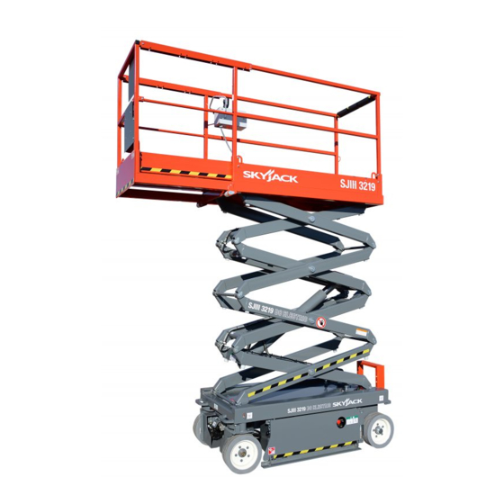
Page 11: Work Platform Major Component Identification
Work Platform Major Component Identification OPERATOR’S CONTROL BOX EXTENSION PLATFORM MAIN PLATFORM LIFTING MECHANISM BATTERY TRAY HYDRAULIC/ ELECTRIC TRAY POTHOLE PROTECTION BASE DEVICE Figure 1-1. SJIII Series Work Platform (Model 3220 shown) SJIII Series - The COMPACTS & SECTION 1, Page 11 Dec. - Page 12 Notes SECTION 1, Page 12 SJIII Series - The COMPACTS & Dec. 2002 CONVENTIONALS 122908AD...
-
Page 13: Operating Controls Identification
SECTION 2 OPERATION Operating Controls Identification Emergency Battery Disconnect Switch The following descriptions are for identification, explanation and locating purposes only. A qualified operator MUST read and completely understand these descriptions before operating this work platform. Procedures for operating this work platform are detailed in the “Operating Procedures”... -
Page 14: Platform Controls
Base Controls Operator’s Control Box (3215/3219) Figure 2-3b. Base Control Box 3215/3219 Platform Up/Down Selector Switch - This selector type switch raises or lowers the platform to a desired height. Enable Switch - This switch, when activated, brings power to the Lower Base Control Emergency Stop Button - This red “mushroom- head”... -
Page 15: Identification And Operation Of Safety Devices
Pothole Protection Device Lift/Off (If Equipped)/Drive Select Toggle Switch - If “Lift” is selected, the lift circuit is energized. “OFF”(If Equipped) disconnects power from both the lift and drive circuits. If “DRIVE” is selected, the drive circuit is energized. Emergency Stop Button - This red “mushroom- head”... -
Page 16: Operator Qualifications
Operator Qualifications Fold-Down Guardrail System Only trained and authorized persons should use this work platform. Safe use of this work platform requires the operator to understand the limitations and warnings, operating procedures and operator’s responsibility for maintenance. Accordingly, the operator MUST understand and be familiar with this operating manual, its warnings and instructions and... -
Page 17: Operating Procedures
Operating Procedures In the battery tray, check the electrolyte level in all four batteries. If plates are not covered, carefully add distilled or demineralized water. If Set-Up Procedure needed, check the specific gravity in each battery, it should be 1.260 to 1.275. (This Remove all packing materials and inspect for reading will not be correct if you just added water damage incurred during transport. -
Page 18: Section 2 - Operation
Prestart Checks Inspect all hoses, fittings, wires, cables, valves, etc. for leaks, hidden damage and foreign material. Carefully read and completely understand Section 2, OPERATION in this manual and 13A. On (CE) machines: warnings and instruction labels on the work For Models 3215/3219, raise the platform by platform. -
Page 19: Start And Operation
Start And Operation OPERATOR’S CHECKLIST Using the controls on the base: INSPECT AND/OR TEST THE FOLLOWING DAILY OR AT BEGINNING OF EACH SHIFT Turn Emergency Power Disconnect Switch to “ON” position. (CE rated machines pull out OPERATING AND EMERGENCY CONTROLS. Emergency Stop Button located on Base SAFETY DEVICES AND LIMIT SWITCHES. - Page 20 Note To Increase Drive Torque - Toggle The “HIGH/ NORMAL TORQUE” switch to select high torque (low speed) or normal torque (high speed). A lowering warning system is standard on (CE) Models Select “HIGH” position when climbing grades 3215, 3219, 3220 and 3226. This system automatically or when loading or unloading the work platform, stops the lowering function before reaching the fully select “NORMAL ”...
-
Page 21: Emergency Lowering System
Emergency Lowering System Shutdown Procedure Fully lower the platform. Turn Key Switch to “OFF” position. Remove key. Push in Emergency Stop Button. Rotate Emergency Battery Disconnect Switch to “OFF” position. (On CE machines also push in Emergency Stop Button located on Base Control Box.) Figure 2-10. -
Page 22: Winching And Towing Procedures
Winching And Towing Make sure that the work platform is on level ground. Chock or block the wheels to keep work platform from Procedures rolling. Warning • For Left-Hand Brake: Using a adjustable wrench or , rotate the lock-out block on the brake pin When towing, DO NOT drive onto a downward slope... - Page 23 Free-Wheeling Valve Preparation After Winching Or Towing After moving machine, complete the following proce- dures: Position machine on a firm, level surface. Chock or block the wheels to keep work platform from rolling, or engage the parking brake by (Models 3220, 3226 Located at the rear of the base) momentarily activating the drive function.
-
Page 24: Battery Service And Charging Procedures
Battery Service And Charging Battery Charging Procedures Procedures EE-Rated Machines Battery Service Warning Warning Explosion Hazard DO NOT CHARGE BATTERIES IN HAZARDOUS AREA! THE EE-RATING OF A MACHINE DOES NOT INCLUDE THE CHARGING OF BATTERIES. Keep flames and sparks away. DO NOT smoke near batteries. -
Page 25: Battery Charger Operation
Battery Charger Operation Standard Machines Battery Charger 2.1 Warning Explosion Hazard Charges can ignite flammable materials and vapors. DO NOT use near fuels, grain dust, solvents or other flammables. Warning Figure 2-13. Battery Charger 2.1 Shock Hazard (SK2440E Shown) 1 Green LED To reduce the risk of electrical shock, the charger 2 Yellow LED must only be connected to properly grounded single... -
Page 26: Battery Charger 2.2
Battery Charger 2.2 If the “80% CHARGE” light continues to stay on after the charge cycle is complete, this indicates to the operator that the batteries are not capable of attain- ing a full charge. If the “INCOMPLETE” light remains on after the charge cycle is complete, this indicates to the operator that the batteries are not capable of attaining even an 80% charge. -
Page 27: Battery Charger 2.3
Battery Charger 2.3 3. The charging time is affected by numerous factors including battery Amp-Hour capacity, depth of discharge, battery temperature, and battery condition (new, old, or defective). Batteries larger than 240 Ah can be recharged but will take longer. Danger Do not disconnect the DC output wires near the batteries when the charger is ON. - Page 28 If all 3 LEDs blink together, there is a problem. Take proper action according to the following instructuions: 3 LEDs blink once simultaneously: Output connection error. Check the battery and charger connection. The output may not be connected to the batteries or the connections to the batteries may have corroded or loosened.
- Page 29 Table 2-1. Owner’s Annual Inspection Record MODEL NUMBER________________________________ SERIAL NUMBER________________________ RECORDING DATE RECORDING YEAR # OWNER’S NAME INSPECTED Table 2-2. Maximum Platform Capacities (Evenly Distributed) With 3’ Extension Platform With Powered Extension Platform MODEL Main Platform Extension Platform Main Platform Extension Platform 350 lbs.
- Page 30 Table 2-3. Maintenance And Inspection Schedule Daily Weekly Monthly 3 Months 6 Months 12 Months* Mechanical Structural damage/welds Parking brake Tires/wheels & fasteners A, B & C A, B & C Guides/ rollers & slider pads A, B & I A, B &...
- Page 31 Table 2-4. Floor Loading Pressure (SJIII Conventionals) 3215 3219 3220 / 3220m 3226 / 3226m MODELS 3490 4840 4110 4610 2400 3000 2580 3130 (min) (max) (min) (max) (min) (max) (min) (max) 1583 1991 1864 2091 1088 1360 1170 1420 (min) (max) (min)
- Page 32 MOBILE ELEVATING PLATFORMS www.skyjackinc.com...
Need help?
Do you have a question about the SJIII 3215 and is the answer not in the manual?
Questions and answers