Skyjack SJ12 Operating Manual
Vertical mast series (ansi/csa)
Hide thumbs
Also See for SJ12:
- Service manual (143 pages) ,
- Operation manual (84 pages) ,
- Operation and installation manual (36 pages)

Related Manuals for Skyjack SJ12


Summary of Contents for Skyjack SJ12
- Page 1 MODELS SJ 12 Operating Manual Vertical Mast Series (ANSI/CSA) Part No. 155169AB-A September 2010...
- Page 2 Skyjack Service Center 3451 Swenson Ave. St. Charles, Illinois, 60174 USA Phone: 630-262-0005 Toll Free: 1-800-275-9522 Fax: 630-262-0006 Email: service@skyjack.com Parts (North America) Toll Free: 1-800-965-4626 Toll Free Fax: 1-888-782-4825 E-mail: parts@skyjack.com Parts & Service (Europe) Unit 1 Maes Y Clawdd, Maesbury Road Industrial Estate...
- Page 3 The Safety Alert Symbol identifies important safety messages on aerial platform, safety signs This Safety Alert Symbol means attention! in manuals or elsewhere. When you see this symbol, be alert to the possibility of personal Become alert! Your safety is involved. injury or death.
-
Page 4: Table Of Contents
Table of Contents Section 1 - About Your Aerial Platform Read and Heed Aerial Platform Definition .............................7 Purpose of Equipment ..............................7 Use of Equipment ................................7 Manual ..................................7 Operator ..................................7 Service Policy and Warranty ............................7 Optional Accessories ..............................7 Scope of this Manual ..............................7 Safety Rules Operator Safety Reminders ............................8 Electrocution Hazard ..............................9... - Page 5 Table of Contents Section 2 - Operation (Continued) Operator’s Responsibility ..........................23 Visual and Daily Maintenance Inspections .....................24 Function Tests..............................29 Start Operation ..............................35 2.9-1 To Activate Base Control Console ....................35 2.9-2 To Raise or Lower Platform Using Base Control Console ..............35 2.9-3 To Activate Platform Control Console ....................36 2.9-4...
-
Page 6: Purpose Of Equipment
SKYJACK warrants each new Vertical Mast series aerial platform to be free of defective parts and workmanship for the first 24 months. Any defective part will be replaced or repaired by your local SKYJACK dealer at no charge for parts or labor. Contact the SKYJACK Service Department for warranty statement extensions or exclusions. -
Page 7: Safety Rules
Common sense dictates the use of protective clothing when working on or near machinery. Use appropriate safety devices to protect your eyes, ears, hands, feet and body. Any modifications from the original design are strictly forbidden without written permission from SKYJACK. Vertical Mast Series... -
Page 8: Electrocution Hazard
Section 1 - About Your Aerial Platform Safety Rules Electrocution Hazard This aerial platform is not electrically insulated. Maintain a Minimum Safe Approach Distance (MSAD) from energized power lines and parts as listed below. The operator must allow for the platform to sway, rock or sag. This aerial platform does not provide protection from contact with or proximity to an electrically charged conductor. -
Page 9: Safety Precautions
Safety Rules Section 1 - About Your Aerial Platform Safety Precautions Know and understand the safety precautions before going on to next section. wARNiNG Failure to heed the following safety • DO NOT increase the lateral precautions could result in tip over, surface area of the platform. - Page 10 Section 1 - About Your Aerial Platform Safety Rules Safety Precautions (Continued) Know and understand the safety precautions before going on to next section. • DO NOT operate on surfaces not capable of holding the weight of the aerial platform including the rated load, e.g., covers, drains, and •...
- Page 11 • DO NOT place materials on the guardrails or materials that exceed the confines of the guardrails unless approved by Skyjack. • DO NOT operate if aerial platform working properly or if any parts are damaged or worn.
-
Page 12: Section 2 - Operation
• has been damaged or appears to have worn or Skyjack recommends the use of a fall restraint missing parts. system to keep an occupant within the confines •... -
Page 13: Operator Qualifications
Section 2 - Operation General 2.0 Operation • The operator must be sure that the aerial platform This section provides the necessary information needed has been properly maintained and inspected to operate the aerial platform. It is important that the user before using it. -
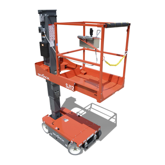
Page 14: Major Components
Major Components Section 2 - Operation 2.2 Major Components Platform Repositioning Handle Platform Control Console Foot Pedal Platform Mast - Lifting Mechanism Hydraulic/Electrical Compartment Access Door Base SKYJACK Vertical Mast Series Aerial Platform Vertical Mast Series Page 16 December 2007... -
Page 15: Major Assemblies
Section 2 - Operation Major Assemblies 2.3 Major Assemblies 2.4 Serial Number Nameplate The aerial platform consists of three major assemblies: The serial number nameplate, located at the rear of the base, lifting mechanism and platform. aerial platform, lists the following: 2.3-1 Base •... -
Page 16: Component Identification
Component Identification Section 2 - Operation 2.5 Component Identification 2.5-3 Base Control Console This control console is located at the rear of the base. The following descriptions are for identification, It contains the following controls: explanation and locating purposes only. 2.5-1 Main Power Disconnect Switch This switch is located at the rear of the base. -
Page 17: Emergency Lowering System
Section 2 - Operation Component Identification 2.5-4 Emergency Lowering System 2.5-6 Hourmeter/Circuit Breaker/Diagnostic This emergency lowering system allows platform Switch lowering in the event of an emergency or an electrical This assembly is located inside the hydraulic/electrical system failure. compartment. Remove any obstructions from a lowering platform. -
Page 18: Platform Control Console
Component Identification Section 2 - Operation 2.5-8 Platform Control Console 2.5-9 AC Outlet on Platform This removable control console is mounted at the right This outlet is a source of AC power on the platform. front of the platform. It contains the following controls: Figure 2-8. -
Page 19: 11 Pothole Protection Device
Section 2 - Operation Component Identification 2.5-11 Pothole Protection Device 2.5-12 Lanyard Attachment Anchorage Figure 2-10. Pothole Protection Device Pothole Protection Device - This device consists of a set of mechanically actuated steel weldments located under the base. These weldments will automatically rotate for reduced ground clearance Figure 2-11. -
Page 20: 13 Platform Maintenance Lock Mechanism
Component Identification Section 2 - Operation 2.5-13 Platform Maintenance Lock Mechanism This locking mechanism is located underneath the platform. Figure 2-12. Platform Maintenance Lock The aerial platform is equipped with a maintenance lock mechanism. When engaged, it allows access to the hydraulic/electrical compartment. During this access, it disables all functions. -
Page 21: Operator's Responsibility
Section 2 - Operation Component Identification 2.6 Operator’s Responsibility impORTANT If aerial platform is damaged or any It is the responsibility of the operator, prior to each work unauthorized variation from factory- shift, to perform the following: delivered condition is discovered, aerial 1. - Page 22 Component Identification Section 2 - Operation Mast Platform Base 2.7 Visual & Daily Maintenance Inspections 2.7-2 Electrical Begin the visual and daily maintenance inspections by Maintaining the electrical components is essential to good checking each item in sequence for the conditions listed performance and service life of the aerial platform.
- Page 23 Section 2 - Operation Component Identification (Special Options) Main Power Disconnect Switch Base Control 110/220V Outlet Switches Receptacle Pothole Protection Battery Charger Wheel/Tire Assembly Device 2.7-5 Base • Wheel/Tire Assembly The aerial platform is equipped with solid • Main Power Disconnect Switch rubber tires.
- Page 24 Operator’s Responsibility Section 2 - Operation AC Outlet Manuals Box Platform Assembly Lanyard Attachment Anchors Platform Control Console 2.7-6 Platform Assembly • Platform Control Console Ensure all switches and controller are returned to neutral and are properly wARNiNG secured. Ensure that you maintain three points of Ensure there are no loose or missing parts contact to mount/dismount platform.
- Page 25 Section 2 - Operation Operator’s Responsibility Hydraulic Pump and Motor Batteries Hydraulic Main Manifolds Tank 2.7-7 Hydraulic/Electrical Compartment e. Replace battery if damaged or incapable of holding a lasting charge. 1. To access the hydraulic/electrical compartment, refer to Section 2.14. wARNiNG Use original or manufacturer-approved •...
- Page 26 Start Operation Section 2 - Operation Cables (Rear) Motor Controller Tilt Sensors Mast Assembly Chains (Front) Pothole Protection Device • Hydraulic Oil 2.7-8 Lifting Mechanism Ensure platform is fully lowered, and then • Mast Assembly visually inspect the hydraulic oil level Ensure mast assembly shows no visible •...
-
Page 27: Function Tests
Section 2 - Operation Start Operation Main Power Disconnect Switch Base Emergency Stop 2.8 Function Tests 2.8-2 Base Control Console Function tests are designed to discover any malfunctions 1. Turn main power disconnect switch to “ ” on before aerial platform is put into service. The operator position. - Page 28 Start Operation Section 2 - Operation Base Control Console Emergency Lowering • Test Off/Platform/Base Switch • Test Lower/Neutral/Raise Switch 1. Select and hold off/platform/base key switch wARNiNG Be aware of overhead obstructions to “ ” base position and “ ” raise the or other possible hazards around the platform with lower/neutral/raise switch.
- Page 29 Section 2 - Operation Start Operation Base Control Console Emergency Lowering 2.8-3 Test Platform Maintenance Limit Switch 2.8-4 Platform Control Console 1. Traverse the platform to maintenance position, 1. Ensure main power disconnect switch is in “ ” refer to Section 2.14.
- Page 30 Start Operation Section 2 - Operation Rocker Switch Controller Lift/Drive/Steer Enable Trigger Switch Emergency Stop Button/ Operation Light Lift/Off/Drive Switch Horn Pushbutton • Test Platform Emergency Stop • Test Steering 1. Push in “ ” emergency stop button and 1. Select lift/off/drive switch to “ ”...
- Page 31 Section 2 - Operation Start Operation Rocker Switch Controller Lift/Drive/Steer Enable Trigger Switch Emergency Stop Button/ Operation Light Lift/Off/Drive Switch Horn Pushbutton • Test Driving • Test Brakes 1. Ensure path of intended motion is clear. wARNiNG Brakes will engage instantly when you 2.
- Page 32 Start Operation Section 2 - Operation Rocker Switch Controller Lift/Drive/Steer Enable Trigger Switch Emergency Stop Button/ Operation Light Lift/Off/Drive Switch Horn Pushbutton • Test Horn • Test Pothole Sensor 1. Push “ ” horn pushbutton. wARNiNG Result: Horn should sound. Ensure that you maintain three points of contact to mount/dismount platform.
-
Page 33: Start Operation
Section 2 - Operation Start Operation Start Operation 2.9-1 To Activate Base Control Console Carefully read and completely understand the operating manual and all warnings and instruction labels (refer to wARNiNG labels section) on the aerial platform. Ensure that you maintain three points of contact to mount/dismount platform. -
Page 34: To Activate Platform Control Console
Start Operation Section 2 - Operation 2.9-3 To Activate Platform Control Console Return controller to neutral center position to stop. Release “ ” enable trigger switch. Turn main power disconnect switch to “ ”on position. wARNiNG To protect against unintended movement of On base control console, pull out “... -
Page 35: To Steer
Section 2 - Operation Start Operation 2.9-6 To Steer 2.9-7 Shutdown Procedure On platform control console, select lift/off/drive Completely lower the platform. switch to drive “ ” position. On platform control console, push in “ ” emergency stop button. Activate and hold “ ”... -
Page 36: Loading/Unloading
Loading/Unloading Section 2 - Operation 2.10 Loading/Unloading 2.10-1 Driving Before driving the aerial platform: Know and heed all national, state or territorial/provincial and local rules which apply to your loading/unloading • Ramp or dock capacity should be sufficient to of aerial platforms. withstand maximum aerial platform weight. -
Page 37: Lifting
Section 2 - Operation Winching and Towing Procedures 2.10-2 Lifting NOTE The mass of the aerial platform is as Table 2.3. The center of gravity is wARNiNG approximately located in the middle of the Only qualified rigger shall operate aerial platform, front to back and side to machinery during lifting. -
Page 38: Winching And Towing Procedures
Winching and Towing Procedures Section 2 - Operation 2.11 Winching and Towing Procedures wARNiNG This section provides the operator with procedures Brakes must be manually disengaged for about towing and winching and on how to manually pushing, winching or towing. release the brakes. -
Page 39: Emergency Lowering Procedure
Section 2 - Operation Emergency Lowering Procedure 2.12 Emergency Lowering Procedure This section guides the operator on how to use the emergency lowering system. This system allows platform lowering in the event of an emergency or an electrical system failure. wARNiNG Keep clear of lifting mechanism when using emergency lowering valve. -
Page 40: Platform Traversing (If Equipped)
Platform Traversing Procedure Section 2 - Operation 2.13 Platform Traversing Locate platform maintenance locking mechanism underneath the platform. To traverse platform, step on the foot pedal on Unlatch maintenance locking mechanism by the platform (item 1) and grasp the platform pulling and holding the handle (item 2), then pull repositioning handle (item 2) then carefully the platform fully to the maintenance position. -
Page 41: Battery Maintenance
Battery Maintenance Section 2 - Operation 2.15 Battery Maintenance 2.15-2 Battery Charging Operation This section provides the operator with procedures on how to service and charge the battery. This also provides charger operation instructions. 2.15-1 Battery Service Procedure wARNiNG Explosion Hazard - Keep flames and Figure 2-22. - Page 42 Section 2 - Operation Battery Maintenance The charging time is affected by numerous 3 LEDs blink once simultaneously: factors including battery Amp-Hour capacity, Output connection error. Check the battery and charger depth of discharge, battery temperature, and connection. The output may not be connected to the battery condition (new, old or defective).
-
Page 43: Standard And Optional Features
Tables Section 2 - Operation Table 2.1 Standard and Optional Features Models SJ12 S T A N D A R D E Q U I P M E N T Full Height Maximum drive height Variable speed, front two wheel hydraulic drive 90°... -
Page 44: Tables
Do not use the aerial platform if an inspection has not been recorded in the last 13 months. This decal must be completed, dated and signed, after each inspection time interval as stated above. Table 2.3 Specifications and Features MODEL SJ12 1720 Ib. Weight 30 in. -
Page 45: Maximum Platform Capacities (Evenly Distributed)
Section 2 - Operation Table 2.4 Maximum Platform Capacities (Evenly Distributed) Tilt Maximum Wind MODEL Capacity Cutout Speed Setting SJ12 500 lb. 2 Person(s) 28 mph 1.5 x 3 267AA Table 2.5 Floor Loading Pressure Total Aerial Total Aerial Platform Load... -
Page 46: Floor Loading Pressure
Intermixing tires of different types or using tires of types other than those originally supplied with this equipment can adversely affect stability. Therefore, replace tires only with the exact original Skyjack-approved type. Failure to operate with matched approved tires in good condition may result in death or serious injury. -
Page 47: Maintenance And Inspection Schedule
B - Perform Scheduled Maintenance Inspection. Refer to Service & Maintenance manual. * - Maintenance must be performed only by trained and competent personnel who are familiar with mechanical procedures † - Refer to Skyjack's website @ www.skyjack.com for latest service bulletins prior to performing quarterly or yearly inspection. wARNiNG Use original or equivalent to the original parts and components for the aerial platform. -
Page 48: Operator's Checklist
Hourmeter Reading: Operator's Name (Printed): Date: Time: Operator's Signature: Each item shall be inspected using the the appropriate section of the Skyjack operating manual. As each item is inspected, check the appropriate box. INSPECTION FREQUENCY - PASS FREQUENTLY - FAIL... - Page 49 Wheel Load Indicates rated wheel load. Forklift Pocket Insert fork fully into pocket to lift aerial platform. Skyjack Logo Small Skyjack logo - blue and red Skyjack Logo Small Skyjack logo - blue Vertical Mast Series Page 52 December 2007...
- Page 50 Section 2 - Operation Labels Labels - Model SJ12 Right View Label Pictorial Description Annual Inspection Ensure that work platform has received annual inspection prior to operation. Manual Storage Box Indicates location of operating manual. Model Number* Product Idenifiter *Model number will vary, may not be as shown.
- Page 51 Section 2 - Operation Labels - Model SJ12 Right View (Continued) Label Pictorial Description Skyjack Logo Small Skyjack logo - blue and red Skyjack Logo Small Skyjack logo - blue Lanyard Anchorage Point Attach anchorage harness lanyard here. Connect Platform AC Supply Connect AC power supply here for platform accessory outlet.
- Page 52 Section 2 - Operation Labels Labels - Model SJ12 Rear View Label Pictorial Description Lift and Tie Down Points Only use these points for lifting or tying down. Base Controls Select “ ” to lower or “ ” raise platform.
- Page 53 Labels Section 2 - Operation Labels - Model SJ12 Rear View (Continued) Label Pictorial Description Towing/Pushing Procedure Follow this procedure to tow/push the aerial platform. Emergency Main Power Disconnect Rotate clockwise to turn on emergency main power; rotate counterclockwise to turn off emergency main power; insert padlock to lock in position.
- Page 54 Section 2 - Operation Labels Labels - Model SJ12 Front View Label Pictorial Description Hazard Idenification Read and understand the outlined risks associated with this work platform prior to operation. Horizontal Load Rating & Platform Capacity* Operating with rated work load in each configuration below indicated wind speed only.
- Page 55 Labels Section 2 - Operation Labels - Model SJ12 Front View (Continued) Label Pictorial Description Standards Compliance Indicates standards to which the work platform complies. Lift and Tie Down Points Only use these points for lifting or tying down. No Jewelry Caution - Do not wear jewelry.
- Page 56 Section 2 - Operation Labels Labels - Model SJ12 Base View Inside View Top View Label Pictorial Description Warning - Do Not Alter Aerial platform altering warning Hydraulic Oil ATF Dexron III Replace hydraulic fluid with ATF Dexron III only.
- Page 57 Labels Section 2 - Operation Labels - Model SJ12 Base View (Continued) Inside View Top View Label Pictorial Description Crushing Hazard Danger - Crushing hazard Diagnostic Switch Enables hydraulic functions for maintenance service. Read “ ” operating manual. Power Circuit Breaker Push to reset power circuit breaker.
- Page 58 Section 2 - Operation Labels Labels - Model SJ12 Platform Control Console Label Pictorial Description Platform Control Console Read “ ” operating manual. Squeeze “ ” trigger to enable controller. Operate “ ” rocker switch to steer. Move controller handle forward to “...
- Page 59 Labels Section 2 - Operation Labels - Model SJ12 Base - Top View Label Pictorial Description Warning - Do Not Open Do not access hydraulic/electrical compartment while platform is elevated. Platform Traversing Procedure Follow this procedure to reposition platform. Read “...
- Page 60 Reliable lift solutions by people who care. www.skyjack.com...
Need help?
Do you have a question about the SJ12 and is the answer not in the manual?
Questions and answers