Table of Contents
Advertisement
OPERATING MANUAL
This manual MUST be kept and stored with the aerial platform at all times.
For Service please call .....................................................................
Skyjack Inc. Service Center 3451 Swenson Ave., St. Charles, IL. 60174 .... FAX 630 262-0006
For Parts in North America and Asia please call ....................................
Skyjack Inc. Parts Center 3451 Swenson Ave., St. Charles, IL. 60174 .............. FAX 888 782-4825
For Parts & Service in Europe please call ....................................................
Skyjack Europe Communicatieweg 29, 3641 SG Mijdrecht Netherlands ............. FAX 31 297 256 948
117131AH
Printed in Canada
TM
800 275-9522
800 965-4626
31 297 255 526
Mar. 2002
Advertisement
Table of Contents

Subscribe to Our Youtube Channel
Related Manuals for Skyjack SJ-8831FE


Summary of Contents for Skyjack SJ-8831FE
- Page 1 This manual MUST be kept and stored with the aerial platform at all times. 800 275-9522 For Service please call ..............Skyjack Inc. Service Center 3451 Swenson Ave., St. Charles, IL. 60174 ..FAX 630 262-0006 800 965-4626 For Parts in North America and Asia please call ........
- Page 2 WARNING This Operating Manual and the “ANSI/SIA Manual Of Responsibilities” are considered fundamental parts of the elevating work platform. They are a very important way to communicate necessary safety information to users and operators. A complete and legible copy of these manuals MUST BE KEPT ON THE WORK PLATFORM in the provided weather resistant storage compartment at all times.
-
Page 3: Table Of Contents
Table Of Contents Section - Paragraph Page No. Section 1 - Introduction Purpose Of Equipment ........................7 Use Of Equipment ..........................7 Warnings ............................7 Description ............................7 Operator Warnings ........................... 8 Specifications And Features ......................9 Standard Features And Optional Equipment ................10 Work Platform Major Component Identification ................ - Page 4 You, as a careful operator, are the best insurance against an accident. Therefore, proper usage of this work platform is mandatory. The following pages of this manual should be read and understood completely before operating the work platform. Any modifications from the original design are strictly forbidden without written permission from SKYJACK, Inc. DANGER ELECTROCUTION HAZARD THIS MACHINE IS NOT INSULATED.
- Page 5 SKYJACK, Inc. warrants each new SJ800E Series work platform to be free of defective parts and workmanship for the first 12 months. Any defective part will be replaced or repaired by your local SKYJACK dealer at no charge for parts or labor.
- Page 6 (4) hours. If a part to Skyjack within 15 days from the time of billing. has serviceable components, PLEASE replace the bad When work platforms are put into stock, the warranty component.
-
Page 7: Section 1 - Introduction
INTRODUCTION Purpose Of Equipment Base The base is a rigid one-piece weldment which The SKYJACK SJ-800E Series Work Platform is supports two component side cabinets. One cabinet designed to transport and raise personnel, tools and contains the hydraulic components, up/down materials to overhead work areas. -
Page 8: Operator Warnings
Optional Accessories Warning The SKYJACK SJ-800E Series Work Platform is Work Platform Conditions designed to accept a variety of optional accessories. These are listed in (Table 1-2.) Standard Features and Optional Equipment. Operating instructions for An Operator Should Not Use Any... -
Page 9: Specifications And Features
Table 1-1. Specifications and Features 8831E 8831FE 8841E 8841FE 10,515 lbs. 11,015 lbs. 11,440 lbs. 11,940 lbs. Weight* (4780kg) (5007 kg) (5200 kg) (5427 kg) 87.0” Width (2.21m) 137.5” Length (3.5m) Platform 68” x 133.5” Size (1.73 x 3.39m) 37.0’ 47.0’... -
Page 10: Standard Features And Optional Equipment
Table 1-2. Standard Features And Optional Equipment Standard Features (ANSI & CE) • Operator Horn • Joystick Control • Diamond Pattern, All Steel Platform Deck Construction • Access Ladders and Gates at Both Sides of Platform • Flashing Light and Descent Alarm •... -
Page 11: Work Platform Major Component Identification
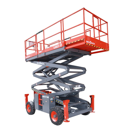
PLATFORM (optional) MAIN PLATFORM LIFTING MECHANISM BATTERY TRAY HYDRAULIC/ ELECTRIC SIDE CABINET BATTERY CHARGER/ HYDRAULIC TANK SIDE CABINET BASE Figure 1-1. SKYJACK SJ-800E Series Work Platform (Model 8841FE shown) SJ-800E Series Battery Powered Mar. 2002 SECTION 1, Page 11 117131AH... -
Page 12: Section 2 - Operation
SECTION 2 OPERATION Operating Controls Identification Emergency Battery Disconnect The following descriptions are for identification, explanation and locating purposes only. A qualified operator MUST read and completely understand these descriptions before operating this work platform. Procedures for operating this work platform are detailed in the “Operating Procedures”... -
Page 13: Base Control Station
1500W AC Inverter (Option) Base Control Station Figure 2-3A. Base Control Station (ANSI & CSA) Figure 2-4. 1500W AC Inverter Inverter - The inverter is located on the base of the machine, it has the following controls. 1. ON/OFF Switch - This slide switch will activate or terminates inverter function. -
Page 14: Platform Controls
Platform Controls 6- Lift/Off/Drive Select Toggle Switch - If “Lift” is selected, the lift circuit is energized. “OFF” disconnects power from both the lift and drive circuits. Operator’s Control Box If “DRIVE” is selected, the drive circuit is energized. 7- Operator Horn Push-Button - This momentary push-button switch activates an automotive-type horn. -
Page 15: Identification And Operation Of Safety Devices
Identification And Operation Of Fold-Down Guardrail System Safety Devices Manual Safety Bar Figure 2-9. Fold-Down Guardrail System Fold-Down Guardrail System This system when folded down, reduces the shut Figure 2-8. Safety Bar height of the work platform for transporting and travelling through doorways. -
Page 16: Operator Qualifications
Operator Qualifications Warning Explosion Hazard Only trained and authorized persons should use this work platform. Safe use of this work platform requires Keep flames and sparks away. DO NOT smoke near the operator to understand the limitations and batteries. warnings, operating procedures and operator’s First Aid responsibility for maintenance. -
Page 17: Prestart Checks
Release the Safety Bar from it’s storage location Check overhead clearances. and swing down into position. (Refer to label on base for proper procedure.) Lower the platform Make sure the batteries are fully charged. until the scissor assembly is firmly supported Disconnect the AC charger cord from the by the safety bar. -
Page 18: Start And Operation
Start and Operation To Drive Forward or Reverse: Select “DRIVE” position with the Lift/Off/Drive Toggle Switch. Using the controls on the base: Depress and hold the Enable push-button, then lift the controller lock ring and push the controller Ensure that the Emergency Battery Disconnect handle forward or backwards. -
Page 19: Emergency Lowering System
Emergency Lowering System Shutdown Procedure Fully lower the platform. Turn Key Switch to “OFF” position. Remove key. Push in Emergency Stop Button. Push in Emergency Stop Button located on Base and remove key. It is not necessary to separate the Emergency Battery Disconnect connectors at work platform shutdown Figure 2-11. -
Page 20: Winching And Towing Procedures
Winching and Towing Procedures Warning DO NOT manually disengage the parking brakes if Warning the work platform is on a slope. When Towing, DO NOT drive onto a downward slope or brake the towing vehicle rapidly. Preparation for Winching Or Towing Parking Brake System Figure 2-13. -
Page 21: Outrigger Operating Procedures
Outrigger Operating Procedures NOTE: (Machines with Outrigger Option) If the platform will not lift and alarm sounds (if Before Operation equipped), MACHINE IS NOT LEVEL or outriggers are not properly set! Make necessary adjustments Check overhead clearances and ground to level machine!) obstructions. -
Page 22: Electrical Inverter (Option)
Battery Service And Charging Electrical Inverter (Option) Procedures Turn the main disconnect switch to the “ON” Battery Service position. Warning Turn the “ON/OFF” switch located on the front Explosion Hazard face of the inverter to the “ON” position. Pull out the “EMERGENCY STOP” switch located Keep flames and sparks away. -
Page 23: Battery Charger Operation
Battery Charger Operation Warning Bycan Charger Shock Hazard To reduce the risk of electrical shock, the charger must only be connected to properly grounded single phase outlet. If charging using 120V, each charger must be plugged into a separate circuit Also, each AC circuit protection should not exceed 15 amperes. -
Page 24: Mac Charger Operation (#Ba1045)
MAC Charger Operation (#BA1045) If the charger is restarted on a fully charged battery pack, the 80% and the “ ” (CHARGER ON) lights will illuminate for approximately 70 minutes. After 70 minutes, the 100% (COMPLETE) light will be illuminated. The charger has a 20 hour timer. If the batteries do not reach approximately 2.55 volts per cell in 20 hours, the “... -
Page 25: Mac Charger Operation (#Ba1001)
MAC Charger Operation (#BA1001) If the “80% CHARGE” light continues to stay on after the charge cycle is complete, this indicates to the operator that the batteries are not capable of attaining a full charge. If the “INCOMPLETE” light remains on after the charge cycle is complete, this indicates to the operator that the batteries are not capable of attaining even an 80% charge. - Page 26 Table 2-1. Owner’s Annual Inspection Record MODEL NUMBER________________________________ SERIAL NUMBER________________________ RECORDING DATE RECORDING YEAR # OWNER’S NAME INSPECTED SJ-800E Series Battery Powered SECTION 2, Page 27 Mar. 2002 117131AH...
- Page 27 Table 2-2A. Maximum Platform Capacities (800E Series) (Evenly Distributed) Manufactured before January 2000. “Meets ANSI/SIA-A92.6 - 1990 Standard” Main First Second Total Platform Extension Extension MODEL Platform Number Of Number Of Number Of Capacity Capacity Capacity Capacity Occupants Occupants Occupants No extension 2500 lbs.
- Page 28 Table 2-2B. Maximum Platform Capacities (800E Series) (Evenly Distributed) Manufactured after January 2000. “Meets ANSI/SIA-A92.6 - 1999 Standard” Main First Second Total Platform Extension Extension MODEL Platform Number Of Number Of Number Of Capacity Capacity Capacity Capacity Occupants Occupants Occupants No extension 2500 lbs.
- Page 29 Table 2-3. Maintenance And Inspection Schedule Daily Weekly Monthly 3 Months 6 Months 12 Months* Mechanical Structural damage/welds Parking brake B &E B & E Tires/wheels & fasteners A, B & C A, B & C Guides/ rollers & slider pads A, B &...
- Page 30 ELEVATING THE WORLD www.skyjackinc.com...
Need help?
Do you have a question about the SJ-8831FE and is the answer not in the manual?
Questions and answers