Table of Contents
Advertisement
Quick Links
OPERATION MANUAL
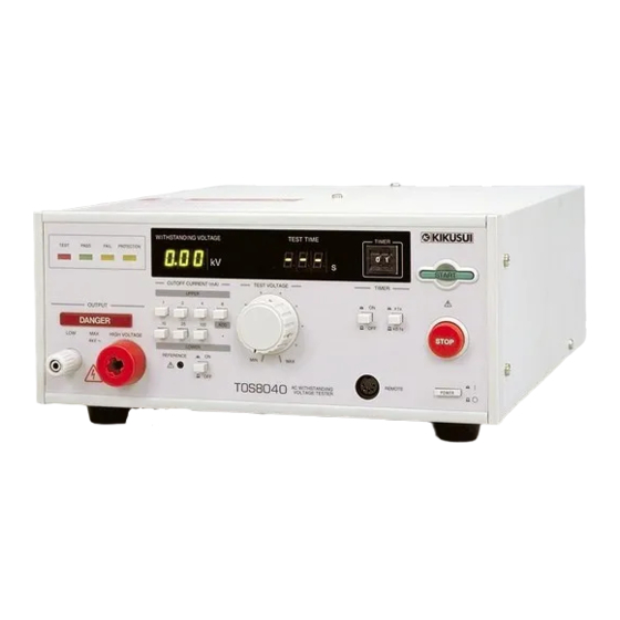
AC Withstanding Voltage Tester
TOS8040
DANGER
This instrument generates high voltage.
• Any incorrect handling may cause death.
• Read "Precautions for Safe Testing" in this manual
to prevent accident.
• Keep this manual near the instrument for easy
access of the operator.
Part No. Z1-AB0-082, IB008603
Oct. 2007
Advertisement
Table of Contents

Subscribe to Our Youtube Channel
Related Manuals for Kikusui TOS8040


Summary of Contents for Kikusui TOS8040
- Page 1 Part No. Z1-AB0-082, IB008603 Oct. 2007 OPERATION MANUAL AC Withstanding Voltage Tester TOS8040 DANGER This instrument generates high voltage. • Any incorrect handling may cause death. • Read “Precautions for Safe Testing” in this manual to prevent accident. • Keep this manual near the instrument for easy...
- Page 2 If you find any incorrectly arranged or missing pages in this manual, they will be replaced. If the manual gets lost or soiled, a new copy can be provided for a fee. In either case, please contact Kikusui distributor/ agent, and provide the “Kikusui Part No.” given on the cover.
-
Page 3: Testing Cannot Be Performed At Unpacking
Testing Cannot be Performed at Unpacking If the TOS8040’s power is turned on in the condition in which the tester has been simply unpacked upon receipt, the interlock function will be acti- vated, preventing performance of testing as-is. See “6.2 Using the INTERLOCK Terminal” (page 45) to operate the tester, taking advantage of the interlock function. -
Page 4: To The Supervisor In Charge Of Operation
• Operating the tester without connecting the grounding wire to ground. • Operating the tester without wearing rubber gloves intended for electrical work. • Approaching a section electrically connected to the output terminal while output is being generated. TOS8040... -
Page 5: Safety Symbols
When this symbol is marked on the product, see the relevant sections in this manual. Protective conductor terminal. Chassis (frame) terminal. On (supply) Off (supply) In position of a bi-stable push control Out position of a bi-stable push control TOS8040 Safety Symbols 3... -
Page 6: Safety Precautions
Always ground the product’s protective conductor terminal to prevent electric shock. Installation • This product is designed for indoor use. Only use it indoors. • When installing products be sure to observe “2.2 Precautions for Installation” described in this manual. 4 Safety Precautions TOS8040... - Page 7 • To maintain performance and safe operation of the product, it is recommended that periodic maintenance, checking, cleaning, and calibration be performed. Service • Internal service is to be done by Kikusui service engineers. If the product must be adjusted or repaired, contact Kikusui distributor/agent. TOS8040...
- Page 8 • The product carries a label providing important safety information. If this label is damaged or the information provided becomes illegible, replace it with a new label. To obtain a new label, please contact your Kikusui distributor or agent. 6 Safety Precautions...
- Page 9 MIN position. IF THIS COLUMN BLANK, THE UNIT IS WIRED IN 220V. SETTING SUPPLY LINE VOLTAGE FREQUENCY VA MAX STANDARD 220V 120V 50 60Hz 100V Always connect the power cordʼs protective conductor terminal to ground. TOS8040 Safety Precautions 7...
- Page 10 Precautions for Safe Testing Gives the precautions to be observed at all times to ensure safe testing. Chapter 4 Part Name’s and Functions Gives the names of switches, terminals, and other controls of the TOS8040. Chapter 5 Panel Operations Describes procedures for testing.
-
Page 11: Table Of Contents
- - - - - - - - - - - - - - - - - - - - - - - - - - - - -32 Tester States and Indications - - - - - - - - - - - - - - - - - - - - - - - - - - - - - - - -33 TOS8040 Contents 9... - Page 12 Setting the Current Detection Lower Reference Limit - - - - - - - - - - - - - - 57 Improvements in Waveform Obtained Using a Zero-start Switch - - - - - - 59 10 Contents TOS8040...
- Page 13 Index ___________________________________________________ 60 TOS8040 Contents 11...
-
Page 14: Chapter 1 General
Features ■ AC withstanding voltage tests of up to 4 kV/100 mA The TOS8040 has a 500 VA high-voltage transformer in the high-voltage power supply section for tests involving a maximum output of 4 kV/100 mA (for 10 minutes maxi- mum). - Page 15 Use this function with the remote control function to automate functions or to reduce actual hands-on testing requirements. ■ Sequence circuit with noise reduction features For reliability, the sequence circuit incorporates thorough noise reduction features to prevent noise-induced malfunctions. TOS8040 General 13...
-
Page 16: Options
Releasing either hand outputs a STOP signal, shutting off the tester’s test voltage. This features are intended to prevent inadvertent output of test voltages when using these probes. HP01A-TOS 14 General TOS8040... - Page 17 FAIL judgments. For more information, see “8.1.4 FAIL MODE” (page 51). High-voltage test leads Model number Maximum usage voltage Cable length Remarks Equivalent of TOS8040 TL01-TOS Approx. 1.5 m 5 kVac (rms) 50 Hz/60 Hz accessory 5 kVdc TL02-TOS Approx.
-
Page 18: Chapter 2 Installation And Preparations For Use
Describes how to unpack the tester for preparation before use. Unpacking Inspection Check the TOS8040 tester upon receipt for any damage that may have occurred dur- ing transit and to confirm that all accessories have been provided. If the product is damaged or if any accessories are missing, notify your Kikusui dis- tributor or agent. -
Page 19: Precautions For Installation
The tester may fall, resulting in damage or injury. ■ Do not use the tester in locations subject to strong magnetic or electric fields. Using the tester in such locations may result in malfunctions, leading to electric shock or fire. TOS8040 Installation and Preparations for Use 17... -
Page 20: Moving Precautions
Checking the supply voltage Before connecting the power cord, check the tester’s supply voltage. The tester’s nominal input rating is indicated on the rear panel. The tester’s standard specifications specify a supply voltage of 220 V. 18 Installation and Preparations for Use TOS8040... - Page 21 Check that the power supply meets the nominal input rating for the tester. Turn the POWER switch off. Connect the power cord to the AC INPUT connector on the tester’s rear panel. Insert the power cord plug into an electrical outlet. TOS8040 Installation and Preparations for Use 19...
-
Page 22: Grounding
* An AC power line is generally a power line connected to an electrical outlet to which the tester’s power cord is connected. Here, it also refers to an AC line con- nected to a privately-owned electrical power generation device. 20 Installation and Preparations for Use TOS8040... -
Page 23: Chapter 3 Precautions For Safe Testing
Wearing Rubber Gloves • When using the tester, always wear rubber gloves intended for electrical WARNING work to prevent electric shock. If you have difficulty obtaining proper rubber gloves, consult your Kikusui distribu- tor or agent. TOS8040 Precautions for Safe Testing 21... -
Page 24: Operating Precautions
Insert the black test lead into the LOW terminal and attach an extraction prevention guard to the terminal, as shown in Fig. 3-2. LOW-side test lead (black) Attach the extraction prevention guard to the terminal and fasten securely. Fig. 3-2 Connecting the LOW-side Test Lead 22 Precautions for Safe Testing TOS8040... - Page 25 Connecting the HIGH VOLTAGE-side test lead ■ To disconnect the test leads from the DUT Disconnect the red test lead from the HIGH VOLTAGE terminal. You do not need to disconnect the black test lead from the LOW terminal. TOS8040 Precautions for Safe Testing 23...
-
Page 26: For High Voltage Output
POWER switch off. ■ Do not turn the POWER switch off. Except in emergencies, do not turn the POWER switch off while output is being generated. 24 Precautions for Safe Testing TOS8040... -
Page 27: Checking Safety After Shutting Off The Output
Disconnect the red test lead from the HIGH VOLTAGE terminal. You do not need to disconnect the black test lead from the LOW terminal. HIGH VOLTAGE-side test lead (red) Fig. 3-8 Disconnecting the HIGH VOLTAGE-side Test Lead TOS8040 Precautions for Safe Testing 25... -
Page 28: When Interrupting Operations
DUT, or other components, take the following two steps. Both must be performed, although either may be performed first. POWER Turn the POWER Disconnect the power plug switch off. from the electrical outlet. Fig. 3-10 Response to Emergencies 26 Precautions for Safe Testing TOS8040... -
Page 29: Stop Using The Tester In The Event Of A Malfunction
• Implement safeguards so that no one will attempt to use the tester before WARNING it has been sent for repair. • Always contact your Kikusui distributor or agent to request repairs. To ensure safety, never attempt to repair the product yourself. TOS8040... -
Page 30: Chapter 4 Part Name's And Functions
Chapter 4 Part Name’s and Functions Gives the names of switches, terminals, and other controls of the TOS8040. Front Panel Fig.4-1 TOS8040 Front Panel [1] POWER switch Turns the tester power on/off. Depressing the switch turns power on ( | ). - Page 31 This voltmeter displays the output voltage, indicating the voltage at the HIGH VOLTAGE terminal. If the tester enters the PROTECTION state, the voltmeter displays the reason for protective function activation by a code ranging from P01 to P12 (7 events). TOS8040 Part Name’s and Functions 29...
- Page 32 The selected setting range (x0.1 / x1) is enabled when the TIMER switch is ON. [14] REMOTE connector Used to start or stop testing from a remote location. For more information, see “6.1 Using the REMOTE Connector” (page 41). 30 Part Name’s and Functions TOS8040...
-
Page 33: Rear Panel
220V 120V 50 60Hz 100V Fig. 4-2 TOS8040 Rear Panel [1] BUZZER knob Adjusts the volume of the buzzer that indicates a FAIL or PASS judgment. Turning the knob clockwise makes the buzzer louder. The buzzer cannot be turned off. -
Page 34: Chapter 5 Panel Operations
After all the display units and TEST TIME indications light, the firmware version is displayed in the test time indicator. Example of indication of version 1.00 Fig. 5-2 Indications Displayed After POWER Switch is Turned On 32 Panel Operations TOS8040... -
Page 35: Tester States And Indications
When lit, this lamp indicates that the test result has been that the test result has been determined to be PASS. determined to be FAIL. (PASS state) (FAIL state) Fig. 5-3 Indicators on the Front Panel TOS8040 Panel Operations 33... -
Page 36: Five States
Press the START switch in this state to start testing. * If the DOUBLE ACTION special test mode is activated, a READY signal is generated for only approx. 0.5 second after the operator operates the STOP switch. 34 Panel Operations TOS8040... -
Page 37: Events Or Conditions That Can Activate The Protection Function
Adjust the output voltage to 4.0 kV or less using the A voltage of 4.3 kV or higher was output. TEST VOLTAGE knob. WI THSTANDING VOLTAGE To cancel the PROTECTION state, press the STOP switch. Fig. 5-4 Example of Display of Code “P06” TOS8040 Panel Operations 35... -
Page 38: Procedure For Test
Setting a Current Detection Upper Reference Limit NOTE • If the operator sets a current value exceeding 50 mA, testing is subject to output time limitations. For more information, see “Footnote *1” in “10.1 Basic Specifi- cations” (page 53). 36 Panel Operations TOS8040... - Page 39 This allows identification of DUTs with exceptionally small leakage current or detection of contact failure or broken wires in the test leads for higher quality withstanding voltage testing. TOS8040 Panel Operations 37...
- Page 40 The voltage set here is applied to the DUT during the test. WARNING • The test voltage must be set by actually outputting the voltage and reading the value on the voltmeter. For safety reasons, disconnect the test leads if they are connected to the output terminals. 38 Panel Operations TOS8040...
- Page 41 Adjust the voltage to a desired value (from 0.05 kV to 4.00 kV). 2. Press the START switch to start test voltage setting. 4. Press the STOP switch to finish test voltage setting. 3. Turn the knob slowly clockwise. Fig. 5-9 Setting the Test Voltage TOS8040 Panel Operations 39...
-
Page 42: Connection To The Dut
START switch. ■ Before disconnecting the test leads from the DUT Confirm that high voltage is not being output, referring to “3.3.3 Checking Safety after Shutting off the Output” (page 25). 40 Panel Operations TOS8040... -
Page 43: Chapter 6 Remote Control
6.1.1 Remote Control with the Optional Remote Control Box The TOS8040 can be controlled from a remote location using an optional remote control box to start or stop testing. Connecting the remote control box to the REMOTE connector on the front panel switches the tester from front panel control to remote control. -
Page 44: Remote Control Using A Control Device
STOP switch on the front panel. Connecting a control device to the REMOTE connector requires a 5-pin, DIN Stan- dard-based connector. Contact your Kikusui distributor or agent if you have diffi- culty obtaining a 5-pin DIN connector. 42 Remote Control... - Page 45 Configure the control circuits so that pins 2 and 3 connect externally. Control circuit example REMOTE connector TOS8040 In this example, controlling the START and STOP con- tacts lets you operate the tester in the same way as from...
- Page 46 Fig. 6-2 appears to be advantageous, in that they are capable of reducing the incidence of noise-induced system malfunctions. The TOS8040 tester has been designed to minimize susceptibility to noise-induced malfunctions, whether originating from the tester itself or from a peripheral device.
-
Page 47: Using The Interlock Terminal
For safety, always enable the interlock function when perform- ing actual testing. To ensure user safety, the TOS8040 interlock function interlocks with external equipment to shut down output. When this function is activated, a PROTECTION state is invoked and output is shut off, preventing further testing. When this function... -
Page 48: Chapter 7 Status Signal Output
This signal is output when the tester is in a PROTECTION state.* * Connecting or disconnecting the REMOTE connector with the FAIL MODE special test mode set to off and the tester in a STOP state will result in no PRO- TECTION signal being output. 46 Status Signal Output TOS8040... -
Page 49: Using The Signal Out Terminals
1 A/30 Vdc screwdriver or the like. Wiring material TOS8040 AWG20 to 26 (1.5 mm Internal circuit of each pair of terminals Rating: +24 V, 100 mA COMMON has the same potential as the chassis. -
Page 50: Example: Use Of Signals
7.2.2 Example: Use of Signals ■ Driving a DC buzzer using a FAIL signal Closed at FAIL judgment TOS8040 Buzzer 30 V or less FAIL 1 A or less Fig. 7-2 Example: Use of FAIL Signal ■ Driving a lamp using an H.V ON signal... -
Page 51: Chapter 8 Special Test Modes
Explains the special test modes. Four Test Modes Four special TOS8040 tester test modes can be set using TEST MODE switches. Fig. 8-1 shows the standard switch configuration (default factory settings). Moving switches 1 to 4 from the standard position to the ON position permits selec- tion of the following four modes. -
Page 52: Pass Hold
START switch on the front panel during testing. Use this function with the optional RC02-TOS (remote control box requiring two- hand operations) for even higher safety. Set switch 3 to ON. Fig. 8-4 Setting the MOMENTARY Test Mode 50 Special Test Modes TOS8040... -
Page 53: Fail Mode
STOP switch. This function is useful for confirming a FAIL state when using the optional high- voltage probe HP01A-TOS or HP02A-TOS. Set switch 4 to ON. Fig. 8-5 Setting FAIL MODE Test Mode TOS8040 Special Test Modes 51... -
Page 54: Chapter 9 Maintenance And Calibration
Please contact your Kikusui distributor or agent to purchase accessories. Calibration The TOS8040 tester is calibrated appropriately on shipment from the factory. How- ever, the tester should be calibrated after long-term usage. • The tester generates voltages as high as 4 kV. Because internal inspec-... -
Page 55: Chapter 10 Specifications
Chapter 10 Specifications Provides the electrical and mechanical specifications for the TOS8040. The specifications are based on the following conditions and settings, unless other- wise specified. • Warm-up time: 30 minutes ° ° • Temperature: 5 C to 35 •... - Page 56 *7 When the lower reference value is 1/2 of the upper reference limit (i.e., the variable resistor is turned fully clockwise). No calibration is made for other values. *8 Voltage required to make FAIL judgment with the output terminals short-circuited due to internal resistance in the output circuit. 54 Specifications TOS8040...
-
Page 57: 10.2 Other Functions
220 V (200 V to 240 V), 120 V (110 V to 130 V), or 100 V (90 (Input voltage range) V to 110 V), 50 Hz or 60 Hz At no-load 50 VA or less (in READY state) Power consumption At rated load 650 VA maximum TOS8040 Specifications 55... -
Page 58: 10.4 Dimensions
320 (330) W x 132 (165) H x 370 (410) D mm Weight Approx. 17 kg • High-voltage test leads TL01C-TOS (approx. 1.5 m): 1 set • Power cord: 1 Accessories • INTERLOCK jumper: 1 • Operation Manual: 1 copy 10.4 Dimensions MAX 330 Unit: mm 56 Specifications TOS8040... -
Page 59: Appendix
Adjust the front panel settings as shown in Fig. A-1. LOWER REFERENCE Disable lower limit judgment. Set TIMER to OFF. Turn the VR all the way counterclockwise using an adjustment screwdriver. Fig. A-1 Preparing to Set the Current Detection Lower Reference Limit TOS8040 Appendix 57... - Page 60 The value of the leakage current is shown with the current detection upper reference normalized to “1.” UPPER: current detection upper reference limit LOWER: current detection lower reference limit Fig. A-2 Flowchart for Setting the Current Detection Lower Reference Limit 58 Appendix TOS8040...
-
Page 61: Improvements In Waveform Obtained Using A Zero-Start Switch
DUT, potentially damaging the DUT or resulting in a FAIL assess- ment for a good DUT. To reduce distortion of test voltage waveforms, the TOS8040 tester uses a zero-start switch semiconductor to open or close a circuit when the supply voltage is near 0 V. - Page 62 READY signal 46 HIGH VOLTAGE terminal 29 READY state 34 high-voltage test lead 15 REMOTE connector 30 high-voltage test probe 14 remote control 41 HP01A-TOS 15 remote control box 14 HP02A-TOS 15 re-testing 40 rubber gloves 21 60 Index TOS8040...
- Page 63 TEST TIME indicator 30 test voltage 38 TEST VOLTAGE knob 30 test voltage waveform 53 time limitations 53 TIMER 30 TIMER switch 30 TL01-TOS 15 TL02-TOS 15 upper reference limit 36 voltmeter 29 window comparator 13 zero-start switch 59 TOS8040 Index 61...
Need help?
Do you have a question about the TOS8040 and is the answer not in the manual?
Questions and answers