
Related Manuals for Crowcon TXgard-IS+


Summary of Contents for Crowcon TXgard-IS+
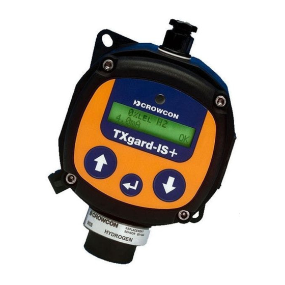
- Page 1 www.acornfiresecurity.com TXgard-IS+ Intrinsically Safe Toxic and Oxygen Gas Detectors Installation, Operation and Maintenance Instructions M07214 Issue 8 January 2015 www.acornfiresecurity.com...
- Page 2 www.acornfiresecurity.com www.acornfiresecurity.com...
-
Page 3: Table Of Contents
Routine maintenance ............23 Sensor replacement and servicing of detectors ....23 6 FAULT FINDING ..............25 Appendices APPENDIX A ................31 WIRING THE TXGARD-IS+ TO CROWCON CONTROL EQUIPMENT ................ 31 APPENDIX B ................35 TXGARD-IS+ SPECIFICATION ..........35 APPENDIX C ................37 SPARE PARTS AND ACCESSORIES ........ - Page 4 www.acornfiresecurity.com APPENDIX D ................38 MENU SYSTEM ..............38 APPENDIX E ................48 4-20 mA LOOPS ..............48 APPENDIX F ................50 CABLING REQUIREMENT ............ 50 APPENDIX G ................53 SENSOR LIMITATIONS ............53 www.acornfiresecurity.com...
-
Page 5: Introduction
Gases include oxygen, carbon monoxide and hydrogen sulphide. For a full list of supported sensors, please contact Crowcon. TXgard-IS+ is a loop-powered instrument providing a 4-20 mA signal suitable for direct connection to a control panel. Unlike most other 4-20... - Page 6 TXgard-IS+ has one top-entry M20 cable entry for customer use as standard. Side entry versions and gland adapters are available (contact Crowcon for details). The Personality Module , mounted on the baseboard, comes in two varieties: Toxic and Oxygen. It converts the sensor output into a standard signal which can be interpreted by the processor.
- Page 7 TXgard-IS+ should be inspected regularly if used in a dusty environment. For further information, please contact Crowcon. Before carrying out any installation work, ensure that local regulations and site procedures are followed.
-
Page 8: Installation
• To detect gases that are lighter than air, detectors should be mounted at high level. Crowcon recommends the use of a Collector Cone (part no. C01051). • To detect gases that are heavier than air, detectors should be mounted at low level. -
Page 9: Mounting
TXgard-IS+ Installation safety and engineering personnel. The agreement reached on the locations of sensors should be recorded. Crowcon is pleased to assist in the selection and siting of gas detectors. 2.2 Mounting TXgard-IS+ should be installed at the location with the detector pointing down. -
Page 10: Electrical Connections
Figure 3 on page 7 , shows the baseboard in detail. The terminals marked J4 should be connected to the control equipment using the appropriate + and – terminals. For further details of wiring the TXgard-IS+ to Crowcon equipment see Appendix A. www.acornfiresecurity.com... - Page 11 www.acornfiresecurity.com TXgard-IS+ Installation Some baseboards may have J4 in this orientation Figure 3: Baseboard TXgard-IS+ is a 4-20 mA sink, loop-powered device designed to work in safe and hazardous zones 0, 1 and 2 areas when used in conjunction with an appropriate barrier. Figures 4, 5 and 6 summarise the electrical connections.
- Page 12 www.acornfiresecurity.com Installation TXgard-IS+ HAZARDOUS AREA Note: An IS earth connection must be supplied in the safe area, so as to avoid earth loops and to maintain IS certification. Figure 5: Electrical connections using Zener barrier www.acornfiresecurity.com...
- Page 13 www.acornfiresecurity.com TXgard-IS+ Installation Figure 6: Electrical connections using galvanic isolator www.acornfiresecurity.com...
-
Page 14: Operation
www.acornfiresecurity.com Operation TXgard-IS+ 3 OPERATION 3.1 The operator display panel and keypad The TXgard-IS+ provides an operator display panel through a Liquid Crystal Display (See Figure 7). The operator display panel allows you to communicate with the TXgard-IS+ instrument through a series of text based menus. -
Page 15: Using The Txgard-Is+ Menus
www.acornfiresecurity.com TXgard-IS+ Operation UNITS Gas being detected % or ppm eg. CO, H2S, O2 5 ppm 4.3mA TXgard-IS+ Loop current Flashing OK indicates system is working Figure 8: LCD ‘operator display panel’ Power V Power: 21.5V Temp: 25.0 C TXgard-IS+ Temperature Figure 9: Power and temperature display (after pressing DOWN key) 3.2 Using the TXgard-IS+ menus... - Page 16 www.acornfiresecurity.com Operation TXgard-IS+ shown in Figure 10 on page 13, detailed menus can be found in Appendix D. NOTE: the menu for the oxygen detector only varies for the ‘Zero/cal gas’ menu item which is replaced by ‘Cal O2 @ 20.9%’. To exit the main menu display ...
- Page 17 www.acornfiresecurity.com TXgard-IS+ Operation www.acornfiresecurity.com...
-
Page 18: Commissioning
www.acornfiresecurity.com Commissioning TXgard-IS+ 4 COMMISSIONING The commissioning procedures for toxic detectors can be found in section 4.1. To commission oxygen detectors go to section 4.2. Warning Before carrying out any work, ensure that local regulations and site procedures are followed. Ensure that the associated control panel is inhibited to prevent false alarms. - Page 19 www.acornfiresecurity.com TXgard-IS+ Commissioning Step 2: Checking the 4-20 mA loop current This step can be omitted as the TXgard-IS+ is delivered pre- calibrated, however, if you wish to check the 4-20 mA loop current, then it can be checked as outlined below. Alternatively the TXgard-IS+ provides a facility to force a known current through the loop.
- Page 20 www.acornfiresecurity.com Commissioning TXgard-IS+ 4 Move the cursor down and select the Zero/Cal gas menu item. The submenu list for zeroing and calibrating the gas appears. 5 Select the Zero gas menu item. The instrument will display a scrolling text message: ‘Ensure the instrument is in clean air and the sensor has settled’.
- Page 21 The panel will display a scrolling text message: ‘Apply calibration gas to instrument ––’. 6 Apply calibration gas (typically half or full scale) to the detector at a flow rate of 0.5 litre/minute. (Crowcon Flow Adaptor part No. C03005) Sticky gases which are rapidly absorbed by connecting pipes (chlorine, nitrogen dioxide and ozone) are applied at 1 litre / minute.
- Page 22 See Table 2 on page 19 for some gases and their typical range. Please note that detectors can be provided in different ranges if required. Contact Crowcon for list of all gases detected. 8 Select the button to set the calibration value.
- Page 23 www.acornfiresecurity.com TXgard-IS+ Commissioning When complete the instrument will report a scrolling text message: ‘Calibration successful! Remove gas from the instrument ––’. 9 Remove the gas from the detector and exit the menu system. The instrument is now calibrated. If the control equipment display requires adjustment, consult the operating manual for the control display equipment.
-
Page 24: Commissioning Procedure
www.acornfiresecurity.com Commissioning TXgard-IS+ 4.2 Commissioning procedure: Oxygen detector Step 1: Connecting the detector to the control panel 1 Apply power to the detector via 2-way connector J4. Figure 1 on page 2. The instrument requires a minimum of 8 V dc at connector J4 at 20 mA. - Page 25 www.acornfiresecurity.com TXgard-IS+ Commissioning Step 3: Calibrate Oxygen NOTE: Unlike previous models it is not necessary to manually “Zero” Oxygen units. 1 Enter the menu system by pressing the button. 2 At the password prompt enter the password, by default this is the down button five times.
- Page 26 www.acornfiresecurity.com Commissioning TXgard-IS+ 7 Press the button to continue and exit the menu system. The instrument is now calibrated. If the control equipment display requires adjustment, consult the operating manual for the equipment. www.acornfiresecurity.com...
-
Page 27: Maintenance
Whilst replacement of sensors or personality modules is permitted by untrained personnel, board-level repairs must be carried out at main Crowcon offices, which are listed on our website at www.crowcon.com. 5.1 Routine maintenance The operational life of the sensors depends on the application, frequency and amount of gas being seen. - Page 28 www.acornfiresecurity.com Maintenance TXgard-IS+ 5.3 Detectors with bayonet type sensor housings NOTE: There is no need to open the main body of the instrument to replace these sensors. 1. Open the sensor housing by pushing in and turning simultaneously to release the bayonet fitting and expose the sensor. 2.
-
Page 29: Fault Finding
www.acornfiresecurity.com TXgard-IS+ Fault finding 6 FAULT FINDING Fatal errors are severe enough that the gas reading cannot be trusted but can sometimes be cleared by removing power and reconnecting it. Non Fatal errors are simply warnings that the instrument has noticed a problem, but can continue / recover by using backup data. - Page 30 www.acornfiresecurity.com Fault finding TXgard-IS+ Symptom / error Cause Solution message “Temp. low err.” The temperature is Ensure temperature is too low or high for between –20˚C and +55˚C “Temp. high err” the instrument to (–4˚F to 131˚F). work reliably. Note: Some sensor types do not work over this entire range.
- Page 31 “mA Calib error” mA calibration data mA calibration must be stored in the checked, using the Ramp mA instrument’s function (see Appendix D), non-volatile and re-calibrated or memory has been instrument must be returned corrupted. to Crowcon for service. www.acornfiresecurity.com...
- Page 32 www.acornfiresecurity.com Fault finding TXgard-IS+ Symptom / error Cause Solution message “FRAM1 fault” FRAMs are non Disconnect power and volatile memory. reconnect it. The FRAM with “FRAM2 fault” The instrument has an error should restore its detected data from backup in the other corruption in one.
- Page 33 www.acornfiresecurity.com TXgard-IS+ Fault finding Symptom / error Cause Solution message “Amplifier error” Personality module has failed (Fatal) and needs replacing “Sensor Fault” Check connections to sensor (Fatal) have not come loose or have been incorrectly wired (Figure 1 on page 2) Alternatively: the instrument cannot see the sensor.
- Page 34 Configuration menu Display blank/ Faulty circuit, LCD Send to Crowcon for cannot be read at or extremely poor reconfiguration any angle contrast setting Error and Fault messages will remain on the operator display panel until they are cleared.
-
Page 35: Appendices
EQUIPMENT This appendix describes how to connect the TXgard-IS+ to the following Crowcon control panels: Vortex, Gasmonitor, Gasmaster and Gasflag. The instructions for connecting the cards and setting the links are outlined below. Connection details for the Ditech range of control equipment will be included on the wiring diagrams supplied for the system. - Page 36 The switch can be found in the hatch on the side of the Quad Channel Module, see Figure 11. Connecting the TXgard-IS+ to a Crowcon Gasmonitor The TXgard-IS+ is connected to the Gasmonitor control panel via an INPUT/OUTPUT MODULE at the rear of the Gasmonitor racking system.
- Page 37 16 15 14 13 12 11 10 9 8 7 6 5 4 3 2 1 Channel Figure 12: Electrical connections for Gasmonitor Connecting the TXgard-IS+ to a Crowcon Gasmaster The TXgard-IS+ is connected to a Gasmaster control panel as shown below. The Gasmaster input channel link should be set to 'SINK' and the input channel should be configured as 'DET 4-20 SINK'.
- Page 38 DETECTOR Gasmaster Detector Input Terminals Figure 13: Connections to a Crowcon Gasmaster 4-20mA/Fire input module Connecting the TXgard-IS+ to a Crowcon Gasflag The TXgard-IS+ is connected to the Gasflag via the screw terminals marked SENSOR +VE (this is the TXgard-IS+ positive supply) and SENSOR SIG (which connects to TXgard-IS+ negative supply).
-
Page 39: Txgard-Is+ Specification
+65˚C, giving out a 4-20 mA signal proportional to measured gas; but LCD will go blank at about –20˚C. The sensor's performance changes at extremes of temperature; consult Crowcon if the detector will be exposed to ambient temperatures below -20˚C or above +40˚C... - Page 40 www.acornfiresecurity.com Appendix B TXgard-IS+ Safety certification Baseefa 08 ATEX 0069X, UL E147777 nos. IECEx BAS 08.0028X "X" Special Conditions for Safe Use: Warning: Static Hazard Clean Only with a Damp Cloth. Standards EN60079-0 (safety in flammable atmospheres) EN60079-11 (intrinsic safety) EN50022 (emissions) IEC61000-4 (immunity) EN50270 (EMC for gas detection equipment)
-
Page 41: Spare Parts And Accessories
Please contact Crowcon for details of the latest replacement sensors. Please quote the part number given on the "Sensor Replacement label" mounted on the outside of the sensor housing. Contact Crowcon for part numbers for suitable Zener Barriers or Galvanic Isolators. -
Page 42: Menu System
www.acornfiresecurity.com Appendix D TXgard-IS+ APPENDIX D MENU SYSTEM This section provides greater details for the TXgard-IS+ menu items and is a supplement to the section 'Using the TXgard-IS+ menus' on page 11. You may wish to refer to the Menu Map on the back cover to familiarise yourself with the menu hierarchy. - Page 43 www.acornfiresecurity.com TXgard-IS+ Appendix D The display should look as follows: Inhibit active Press to go on TXgard-IS+ Gas Calibration Menus Description: The gas calibration menus provide the instructions and means to calibrate the instrument. This menu is different for toxic detectors and oxygen detectors.
- Page 44 www.acornfiresecurity.com Appendix D TXgard-IS+ Menu: (Oxygen detectors) Cal O2 @ 20.9% gas Submenu To main menu Confirm O2 cal Cal O2 @ 20.9% gas This menu provides instructional guidelines to set the oxygen level on an oxygen detector. Note: clean air is always considered to be 20.9% oxygen.
- Page 45 www.acornfiresecurity.com TXgard-IS+ Appendix D Instructions 1. Enter the TXgard-IS+ menu system by pressing the followed by the down key five times. 2. Move the cursor down and select the Ramp mA output menu item by pressing . The display should look as follows; mA: 4.0 (22.7V) Use , to edit TXgard-IS+...
- Page 46 www.acornfiresecurity.com Appendix D TXgard-IS+ Menu: Configuration Submenu To main menu Limit 4-20 mA Set inhibit mA Zero suppress Damping Menu timeout Fatal mA Non-fatal mA Display option LCD Contrast Pwr-on inhibit Help screen Menu item Options Description To Main Menu Exit Exit to main menu.
- Page 47 www.acornfiresecurity.com TXgard-IS+ Appendix D Menu item Options Description Zero suppress None, Minor or Major Defines the size of the dead band about the zero point of the device. This will suppress unwanted spurious signals and improve stability at zero. Suppression may be set to 3 levels, with increasing levels of suppression.
- Page 48 www.acornfiresecurity.com Appendix D TXgard-IS+ Menu item Options Description Fatal mA Minimum, 3 mA, 24 This selects the current the mA or Gas Level instrument will sink when a fatal error has been detected. Note: the option ‘gas level’ is available; this means the instrument will ignore the error for the purposes of loop current - a...
- Page 49 www.acornfiresecurity.com TXgard-IS+ Appendix D Menu item Options Description LCD Contrast Contrast adjustment Pressing the up and down arrows will increase and decrease the display's contrast. Pressing RETURN [copy in symbol from cell above] will return to last menu. Pwr-on inhibit Enable / disable Selects whether the detector output is automatically inhibited for...
- Page 50 www.acornfiresecurity.com Appendix D TXgard-IS+ Menu: Calibrate mA Submenu To main menu Calibrate 4 mA Calibrate 20 mA Instructions The TXgard-IS+ detector provides two test points to measure the signal current. Connect a Digital Volt Meter (DVM) across the test points TP1 and TP2.
- Page 51 www.acornfiresecurity.com TXgard-IS+ Appendix D Clear Faults Description: Clears Faults from display and unit. When the TXgard-IS+ detects a fault, a warning message will be displayed on the operator display panel. Refer to the FAULT FINDING on page 25 to determine cause and solution to the fault. For example, if an instrument detects the line voltage dropping below 8 V, it will flash the warning: Supply voltage low even if the supply voltage recovers, to warn you that there was a problem with the supply.
-
Page 52: Ma Loops
www.acornfiresecurity.com Appendix E TXgard-IS+ APPENDIX E 4-20 mA LOOPS A 4-20 mA loop is a standard method of connecting remote instruments to a control panel. The basic concept is that a reading of zero gas corresponds to 4 mA, and full scale gas corresponds to 20 mA. The control panel supplies typically 24 volts down 2 wires, and measures the current flowing in the loop. - Page 53 www.acornfiresecurity.com TXgard-IS+ Appendix E down the line does not reduce the line voltage below 8 V, which is the minimum working voltage of the TXgard-IS+. See section 2.3 page 5 for further information on cabling requirements. NOTE: It is also possible to have 3-wire current loops. In this case, the instrument is powered by one pair of wires (+ supply and 0 V) and the current signal is measured between the third wire and 0V.
-
Page 54: Cabling Requirement
Cabling to TXgard-IS+ must be in accordance with the recognised standards of the appropriate authority in the country concerned, and must also meet the electrical requirements of the detector. Crowcon recommends the use of 2-core twisted pair cable, but there is no particular restriction as long as it can supply 8 V at 20 mA to the instrument. - Page 55 www.acornfiresecurity.com TXgard-IS+ Appendix F The barrier or isolator will have a maximum permissible set of L, C and perhaps L/R values printed on it. Example: MTL type 728 barrier Voc <=28.12 V, Isc <= 93 mA, Ca <= 0.083 uF, La <= 3.05 mH This means that the barrier output will not exceed 28.12 V or 93 mA into the Hazardous Area, due to the barriers' internal clamps and fuse.
- Page 56 www.acornfiresecurity.com Appendix F TXgard-IS+ cable. Here we can count on 22 V at the control panel, and with a maximum current drain of 20 mA, we will lose (250 + 300 + 36.2 ohms) x 0.02 amps = 11.7 V, so the detector will always have at least 10.3 V.
-
Page 57: Sensor Limitations
SENSOR LIMITATIONS The sensors used in TXgard-IS+ have limitations common to all such gas sensors, and users should be aware of the points listed below. Crowcon can advise on particular situations and suggest alternative sensors if the instrument is likely to experience extreme conditions. - Page 58 www.acornfiresecurity.com Appendix G TXgard-IS+ www.acornfiresecurity.com...
- Page 59 www.acornfiresecurity.com www.acornfiresecurity.com...
- Page 60 www.acornfiresecurity.com www.acornfiresecurity.com...
Need help?
Do you have a question about the TXgard-IS+ and is the answer not in the manual?
Questions and answers