
Related Manuals for Crowcon Vortex FP Compact


Summary of Contents for Crowcon Vortex FP Compact
- Page 1 Vortex FP Compact Flameproof Gas Detection Control System Installation and Operation Manual Issue 1 January 2013...
- Page 2 INTRODUCTION The Crowcon Vortex FP Compact gas detection control system can be installed in Zone 1 or Zone 2 hazardous areas, and is designed to monitor toxic and/or flammable gas detectors, or fire detection devices. The system must be installed and operated in accordance with these instructions.
-
Page 3: Table Of Contents
OPERATION & MAINTENANCE....................6 ......................... 6 PPLYING OWER ..........................7 OMMISSIONING ........................ 7 OUTINE AINTENANCE FP C ................8 ORTEX OMPACT ISPLAY AND ONTROLS TECHNICAL SPECIFICATION....................11 WARRANTY STATEMENT ...................... 12 Vortex FP Compact Installation & Operation Manual Issue 1, January 2013... -
Page 4: Introduction
1.1 S AFETY NFORMATION Vortex FP Compact is a certified Flameproof (Exd) detector suitable for use in ATEX Zone 1 or Zone 2 hazardous areas. Vortex FP Compact must be installed, operated and maintained in strict accordance with these instructions, warnings, label information, and within the limitations stated. -
Page 5: Installation
Care should be taken so as to avoid damage the painted finish of the system. Vortex FP Compact has an ingress protection rating of IP66 and is therefore suitable for outdoor installation. It is recommended however that a suitable sun-shade and rain canopy is fitted. - Page 6 Other cables types may be used provided suitably certified cable glands are also used. Important note: If a Vortex FP Compact system is to be connected to a control system in a safe area (ie control room, plant room etc) it is strongly recommended that the Vortex RS- 485 function terminals are connected to an accessible point in the safe area.
-
Page 7: Operation & Maintenance
OWER Before applying power ensure that any control or shutdown systems to which the Vortex FP Compact is connected are inhibited. AC power supply cables must be connected to the AC terminals shown in Figure 1, with the Live conductor connected to the fused terminal. A wiring diagram is shown on the next page. -
Page 8: Commissioning
If after a settling period faults are reported, check the sensor connections again or refer to Faults table in section 6.4 of the Vortex manual. Vortex FP Compact should display readings for all channels/sensors being monitored. Allow sensors to settle before commencing calibration; refer to sensor instructions supplied with detectors for recommended settling times. -
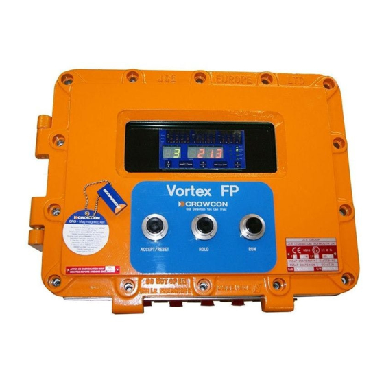
Page 9: Vortex Fp Compact Display And Controls
For more detailed information on Vortex system maintenance, please refer to Section 7 of the standard Vortex manual (part number M07211). It may be necessary to open or remove the lid of the Vortex FP Compact enclosure in order to perform some maintenance functions. Vortex FP Compact must be completely de- energised before the lid is opened;... - Page 10 Channel Test mode, see section 7.4 of the standard Vortex manual. Channel Number Green 7-segment display that normally displays the number of the currently-displayed channel (detector). For the use of this display in Vortex FP Compact Installation & Operation Manual Issue 1, January 2013...
- Page 11 Additional functions are available via buttons fitted to the rear of the display PCB. The button locations and functions are shown below. Warning: access requires the Vortex FP Compact enclosure to be opened; site procedures must be strictly adhered to before attempting to open the enclosure or to operate a powered system with an open enclosure.
-
Page 12: Technical Specification
24Vdc, 2.5A nominal (4.4A max) Operating Temperature: -10 to +40º C (storage temperature -25 to +55ºC) Humidity: 15-90% non-condensing Ingress Protection IP66 CE Approvals Low Voltage Directive EN61010-1:2010 EMC EN50270: 2006 Vortex FP Compact Installation & Operation Manual Issue 1, January 2013... -
Page 13: Warranty Statement
(“CRN”). It is essential that the address label is securely attached to the outer packaging of the returned goods. Units returned to Crowcon as faulty and are subsequently found to be ‘fault free’ or requiring service, may be subject to a handling and carriage charge. - Page 14 Economic & Technological Development Area, Beijing, PRC 100176 +86 10 6787 0335 Email: saleschina@crowcon.com Website: www.crowcon.cn Crowcon reserves the right to change the design or specification of this product without notice. Vortex FP Compact Installation & Operation Manual Issue 1, January 2013...
Need help?
Do you have a question about the Vortex FP Compact and is the answer not in the manual?
Questions and answers