Table of Contents
Advertisement
www.acornfiresecurity.com
IRmax
Infrared hydrocarbon gas detector
Installation, operating and maintenance instructions
Instructions d'installation, d'utilisation et de maintenance
Installations-, Bedienungs- und Wartungsanleitung
Instrucciones de instalación, operación y mantenimiento
Istruzioni d'installazione, uso e manutenzione
Installatie-, bedienings- en onderhoudsinstructies
Instrukcje montażu, obsługi i konserwacji
Instruções de instalação, funcionamento e manutenção
M07028
Issue 5 Jan 2015
www.acornfiresecurity.com
Advertisement
Table of Contents

Related Manuals for Crowcon IRmax


Summary of Contents for Crowcon IRmax
- Page 1 IRmax Infrared hydrocarbon gas detector Installation, operating and maintenance instructions Instructions d’installation, d’utilisation et de maintenance Installations-, Bedienungs- und Wartungsanleitung Instrucciones de instalación, operación y mantenimiento Istruzioni d’installazione, uso e manutenzione Installatie-, bedienings- en onderhoudsinstructies Instrukcje montażu, obsługi i konserwacji Instruções de instalação, funcionamento e manutenção...
- Page 2 www.acornfiresecurity.com www.acornfiresecurity.com...
-
Page 3: Table Of Contents
2.3.2 Installing IRmax using a mounting bracket ......8 2.4 Installing using a spigot gland and auxiliary junction box ....9 2.4.1 To fit IRmax to an auxiliary junction box: ......10 2.5 Cabling requirement ..............10 2.6 Connections and settings .............. 11 3. - Page 4 8. Functional Safety Manual ............... 21 8.1 Introduction .................. 21 8.2 IRmax and IRmax Modbus Safety Function ........21 8.3 Functional Safety Data ..............21 8.4 Hardware Configuration ............... 22 8.5 Software Configuration ..............22 8.6 Systematic Failures ................ 22 8.7 Diagnostic Interval .................
-
Page 5: Irmax Concept
IRmax is compatible with any 4-20mA control system, and can also be installed in an RS485 Modbus addressable network (see Section 7). IRmax requires only 1 Watt of power, typically 75-90% lower than conventional IR gas detectors. -
Page 6: Concept And Safety
IS Barrier module) may be used in environments that may contain hazardous dusts (Zones 21 or 22). • IRmax with an IS Barrier module may be used in Zones 21 or 22 provided the ambient temperature remains below 40°C and a remote IR Display or Hand-Held IR Displays are installed/used outside the hazardous area only. -
Page 7: Product Overview
0 to 100%LEL (Lower Explosive Limit: the minimum concentration in air at which ignition can occur). IRmax is a certified Flameproof (Exd) detector suitable for use in ATEX Zone 1 or Zone 2 hazardous areas. Please refer to the certification label on the side of the Detector to identify the type of certification that relates to the product supplied. -
Page 8: Introduction
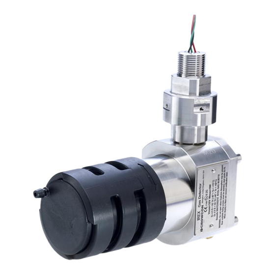
1. Introduction 1.1 General The configuration of each IRmax is identified by a label fitted on the main body. Please quote the product name, part number and serial number when contacting Crowcon for advice or spares. 1.2 Product description IRmax consists of a main body of 316 stainless steel, an antistatic weatherproof cover over the optics and gas measurement chamber and an electronics assembly. - Page 9 ‘ ” ‘ Ž Œ Diagram 3: IRmax exploded view (part numbers shown where applicable) Œ Calibration cap M041007 Weatherproof cap M04995 Ž Mirror retainer Supplied together as ‘mirror replacement kit’ C011206 Mirror ...
-
Page 10: Installation
• The equipment must be earthed using the cable gland and steel armoured cable. • Do not attempt to fit an IR Display to an IRmax not supplied for the purpose. Detectors supplied for use with a display are certified Exd ia, and must be operated either with a Fixed Display containing an IS barrier, or with a Remote IR Display or IS Hand-Held Calibrator connected via a Crowcon IS Barrier module. -
Page 11: Mounting
1. Using the Crowcon mounting bracket with direct field cable connection (4-20mA operation only). 2. Using a spigot gland to connect to an existing Exe or Exd certified junction box. Crowcon supplies a suitable spigot gland as an optional extra (see 3 below). -
Page 12: Terminal Designation
Diagram 5: IRmax with a mounting bracket and cable gland b. If the IRmax is to be mounted on a flat surface, mark and drill two holes using the mounting bracket as a template. Loosely fix two parts of the bracket using fixings suitable for the wall/surface. -
Page 13: Installing Using A Spigot Gland And Auxiliary Junction Box
2. Installation d. Secure the two bracket fixings so that the IRmax is held firmly in place. Re-fit the weatherproof cap. e. Once the IRmax is securely fixed in place, remove the IRmax rear nut to enable access to the cable terminals. -
Page 14: To Fit Irmax To An Auxiliary Junction Box
The maximum recommended cable length is 3.4 km (see Table 1). IRmax requires a dc supply of 12-30Vdc. Ensure there is a minimum of 12V at the IRmax from the control panel, taking into account the voltage drop due to cable resistance at a peak current of 0.1A. -
Page 15: Connections And Settings
Diagram 7. Set to current 'Sink' by fitting the jumper link to pins 3 and 4 as shown on the left-hand photograph. Set to current 'Source' by fitting the jumper link to pins 1 and 2 as shown on the right-hand photograph. IRmax will be set to current 'Sink' unless specified otherwise when ordering. -
Page 16: Operation
The supply voltage is set at the control card as 18 to 30 V. The voltage measured at the IRmax terminals (within the Exe auxiliary junction box if used, or at the IRmax terminal PCB) and must be set between 12 and 30 V. -
Page 17: Routine Maintenance
Each IRmax is supplied pre-calibrated for a particular type of gas (for example methane or propane). If re-calibration for a different gas type is required, the IRmax can be re-configured using the PC communications kit (see Section 5, Accessories and spare parts on page 16), and then calibrated. -
Page 18: Relative Responses Of Gas Types
3. Operation 3.4 Relative responses of gas types The graph below shows the relative responses to other gas types for an IRmax calibrated on methane. Note: many hydrocarbon gases and vapours are more easily detected by IR detectors than methane. The response of IRmax (and other IR gas detectors) will be linear across the 0-100%LEL range for the target gas (ie methane in this example), but non-linear for other hydrocarbons that may also be present. -
Page 19: Specification
158mm x 75mm x 57mm (6.2 x 2.9 x 2.3 ins) (without spigot) Weight IRmax 1.58kg (3.5lbs) IRmax with Fixed IR Display 2kg (4.4lbs) IRmax with IS Barrier Module 2.4kg (5.3lbs) Remote IR Display 0.2kg (0.4lbs) Operating voltage 12Vdc to 30V dc Power <... -
Page 20: Accessories And Spare Parts
2 metres per second. S012130 Mounting bracket kit Enables mounting to a wall or 2" (50 mm) pipe. Not required if IRmax is being fitted to an existing auxiliary junction box. S012152 Sun shade/Collector... -
Page 21: Fault Finding
Check window and mirror, clean if necessary. Re-zero IRmax and check calibration. Any other faults can only be rectified by returning the IRmax to Crowcon or authorised service agent. 6.2 Analogue Output IRmax will remain in Fault state and “Service required” will also be shown on the IR Display (if fitted) if the analogue output signal has failed or is not connected to a control system or load resistor. -
Page 22: Rs485 Modbus Configuration
Connections to the RS485 version of the IRmax must be made via a spigot gland to an auxiliary junction box (see Section 5 on page 16), rather than by cabling directly into the detector. -
Page 23: Wiring Topology
7.2.2 Linear bus connection In a bus-connected topology all IRmax are wired to a linear arrangement, usually with the control panel at one end. A classic situation is a tunnel installation, with IRmax installed at regular intervals (see Diagram 9 below). -
Page 24: Cabling Requirements
IRmax in the line at that value. 2. Each IRmax may draw up to 0.1 A. Calculate the cable voltage loss of the first ‘hop’ between detectors by taking the ‘aggregate current’ to be 0.1A, and multiply this by the cable resistance of the ‘hop’... -
Page 25: Functional Safety Manual
8. Functional Safety Manual 8.1 Introduction The following sections provide detail on the certification of IRmax in accordance with the IEC 61508 and EN 50402 Functional Safety standards. Information is given on the features considered in the safety case, maintenance requirements and data to enable IRmax to be integrated into Safety Instrumented System (SIS). -
Page 26: Hardware Configuration
Tests of the system watchdog are to be accomplished during the annual proof test by power cycling the instrument: IRmax must be power-cycled annually (ie have the 24Vdc supply removed and re-applied) as part of the maintenance programme for the product (refer also to section 3.2). -
Page 27: Environmental
EN60529. The product is designed for continuous operation. 8.10 Hardware fault tolerance The HFT is 0. 8.11 Systematic Capability The IREX/IRmax is of Class SC2. 8.12 Classification The IREX/IRmax is a type B component. www.acornfiresecurity.com Detecting Gas Saving Lives... -
Page 28: Warranty
Crowcon reserves the right to determine a reduced warranty period, or decline a warranty period for any sensor supplied for use in an environment or for an application known to carry risk of degradation or damage to the sensor. - Page 29 Warranty Crowcon reserves the right to apply a handling and carriage charge whereby units returned as faulty, are found to require only normal calibration or servicing, which the customer then declines to proceed with. www.acornfiresecurity.com Detecting Gas Saving Lives...
Need help?
Do you have a question about the IRmax and is the answer not in the manual?
Questions and answers