Crowcon Flamgard-Plus Instructions
Flameproof flammable gas detector with non-intrusive one-man calibration
Hide thumbs
Also See for Flamgard-Plus:
Table of Contents
Advertisement
Quick Links
Instructions
Flamgard-Plus
Flameproof
Flammable Gas
Detector
with Non-intrusive One-man Calibration
1. INTRODUCTION
1.1 Product overview
Flamgard Plus is a flameproof flammable gas detector
suitable for use in zone 1 or 2 hazardous areas. It is designed to detect
flammable gas, present in ambient air, at concentrations not
exceeding the Lower Explosive Limit (LEL) of the target gas for which
it is calibrated. A local display and magnetically operated switches
allow non-intrusive one-man calibration without a hot work permit.
Powered by 24 V dc (nominally) Flamgard-Plus provides a 4-20 mA
signal (sink or source) proportional to the gas concentration and can
also be fitted with optional alarm and fault relays. For a list of
flammable gases that can be detected, please contact Crowcon.
1.2 Product description
Flamgard Plus comprises four parts; 96HD sensor housing, junction box, amplifier and
terminal board. Diagram 1 details Flamgard Plus. The overall assembly is certified EEx d
IIC T6 in Europe and Class 1 , Zones 1&2 AEx d IIC T6 in the USA.
The 96HD sensor housing is a modular stainless steel assembly that
dismantles to allow plug-in pellistor sensors to be replaced easily (see Diagram 4). The
assembly screws into an M20 entry on the junction box.
The junction box is manufactured from marine grade alloy and is supplied with
2 x M20 (1/2" NPT for USA) cable entries for customer use. Alternative cable entries are
available from Crowcon.
The amplifier plugs into the terminal board, and is held in place by two captive
screws. The amplifier provides power to the pellistor sensor, local display and controls,
and a 4-20 mA signal proportional to the gas concentration for connection to a control
panel. To remove, turn screws anti-clockwise and use them to pull amplifier out of the
enclosure.
All electrical connections are made via the terminal board mounted in the base
of the junction box (see Diagram 2). Optional alarm relays (AL1 & AL2) and one fault relay
(FAULT) are mounted on the terminal board which may be used to drive local warning
devices or connect Flamgard-Plus to a control panel.
UNITS
SET BRIDGE VOLTS POT 'A'
TEST POINTS 'A'
1
M20 (
/
" NPT)
2
CABLE ENTRY
STEADY ON
INDICATES
ZERO/ CAL
MODE
ACTIVATED
"UP"
EXTERNAL
EARTH POINT
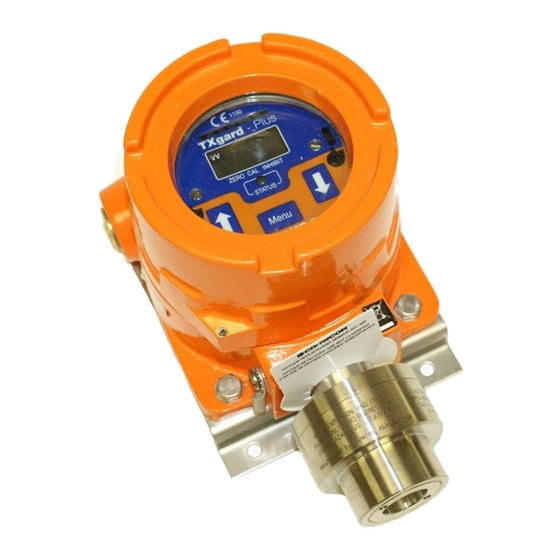
Diagram 1: Flamgard Plus general arrangement
SK
4mA
CONTACT
REVERSING
LINKS
GND
ISOLATE
LINK
ISOLATE
USED FOR
OXYGEN TXGARD.
GND
FOR FLAMGARD
OXYGEN
LINK SET
TO OTHER
CONTROL
EQUIPMENT
TO
96HD
SENSOR
Diagram 2: Terminal and amplifier layouts
1
1
115 (4
/
")
2
SET BALANCE POT 'B'
TEST POINTS 'B'
LEL
1
83 (3
/
")
4
All dimensions in mm unless otherwise stated
REAR VIEW OF
AMPLIFIER
GAS
RANGE
ALARM
SR
OUTPUT
OUTPUT OPTIONS
TEST
INHIBIT
N Y
POINT
17 4 2
40-200 mV
ALARM 1
0V
OTHER
ALARM 2
0V
10-30V
4-20mA
INTERNAL TERMINAL LAYOUT
= ALARM RELAY VERSION ONLY
TAMPER PROOF
GRUB SCREW
(1.5mm ALLEN KEY)
LOCAL
DISPLAY
1
M20 (
/
" NPT)
2
CABLE ENTRY
FLASHING
INDICATES
4-20mA/RELAYS
INHIBITED
ALARM 1 & 2
ADJUSTMENT
POTS
STATUS
LED
"DOWN"
4 OFF
FIXING HOLES
1
O 6mm (
/
")
4
1
HEIGHT = 115 (4
/
")
2
RELAY
CONTACTS
ALARM2
ALARM1
FAULT
ALARM
SET POTS
Advertisement
Table of Contents

Related Manuals for Crowcon Flamgard-Plus


Summary of Contents for Crowcon Flamgard-Plus
- Page 1 A local display and magnetically operated switches allow non-intrusive one-man calibration without a hot work permit. OUTPUT OUTPUT OPTIONS Powered by 24 V dc (nominally) Flamgard-Plus provides a 4-20 mA TEST INHIBIT signal (sink or source) proportional to the gas concentration and can POINT also be fitted with optional alarm and fault relays.
- Page 2 • To detect gases which are lighter than air e.g. methane, detectors should FAULT - Off be mounted at high level and Crowcon recommend the use of a Collector *As standard, AL1 = 20%LEL and AL2 = 40%LEL Cone, Part No. C01051.
- Page 3 Such a device should work satisfactorily for up to 5 years in ideal conditions. Site practices will dictate the frequency with which detectors are tested. Crowcon recommend that detectors be gas tested at least every 6 months and re-calibrated as necessary. To re-calibrate a detector follow steps given in 4.1.
- Page 4 Note: If a spare 96HD sensor housing complete with new sensor is Sensor Element Test point ’A’ Comment available ignore steps f to k and return the old 96HD to Crowcon or an Part no. voltage (mV) approved service centre for repair. S01-637/A...
- Page 5 This product has been tested and found to comply with the European Directive on EMC 89/336/EEC 89/336/EEC Crowcon Detection Instruments Ltd, 2 Blacklands Way, Abingdon Business Park, Abingdon, Oxfordshire OX14 1DY, UK Tel: +44 (0)1235 553057, Fax: +44 (0)1235 553062, email: sales@crowcon.com, internet: http://www.crowcon.com...
Need help?
Do you have a question about the Flamgard-Plus and is the answer not in the manual?
Questions and answers