
Subscribe to Our Youtube Channel
Related Manuals for Crowcon SF6


Summary of Contents for Crowcon SF6
- Page 1 Crowcon F-Gas Detector Infra-Red SF and Refrigerant Gas Detector Installation, Operating and Maintenance Instructions M070029 Issue 2 February 2015...
-
Page 2: Table Of Contents
F-Gas Detector Instructions Table of contents General .......................... 3 Installation........................4 2.1. Operating voltage and analogue outputs (general) ..........4 2.2. Installation....................... 5 2.3. Compensation of the ambient pressure ..............7 Start-up .......................... 7 3.1. Wiring instructions ....................7 3.2. Analogue output: (0)4-20mA ................... -
Page 3: General
F-Gas Detector Instructions 1. General The F-Gas detector provides the benefits of the IR gas sensor technology within a robust enclosure. Rear Casing Interface PCB Front Casing Figure 1: F-Gas Detector Layout The sturdy, IP54-protected casing houses the IR sensor, a user interface with LED status indication and the interface electronics (fig.1). -
Page 4: Installation
Any mechanical damage, such as opening of glued pipe connections or gaskets or the loosening of screws will result in the termination of all liability and warranty granted by Crowcon Detection Instruments Ltd. 2. Installation 2.1. Operating voltage and analogue outputs (general) The F-Gas detector is designed to operate in a range of an input voltage of 12 to 28Vdc. -
Page 5: Installation
F-Gas Detector Instructions The connection of the internal IR sensor module to the interface electronics is via a 4-pin data cable (Fig. 4). The circuit board is screwed to the internal built-in casing from the outside. The IR gas sensor is integrated into this casing to minimize the dead volume and to protect it from any unwanted external effects. - Page 6 F-Gas Detector Instructions The placement of sensors should be determined following advice of experts having specialist knowledge of gas dispersion and the plant processing equipment as well as safety and engineering issues. The agreement reached on the locations of sensors should be recorded. Gently prize-open the flaps using a screw driver being careful to not damage the flaps (see fig.
-
Page 7: Compensation Of The Ambient Pressure
F-Gas Detector Instructions Mount device vertically to the wall using the 4 screw holes (fig. 7) with the cable gland pointing downwards. Figure 7: mounting holes Mounting hole spacing: 127.5mm x 62.5mm. Mounting hole diameter: 4mm. Warning: never install the detector with the front panel facing upwards. Doing so may lead to the IR sensor filter becoming blocked by dust/contaminants which could prevent gas from reaching the sensor. -
Page 8: Analogue Output: (0)4-20Ma
(analogue signal) and GND (0V) terminals. The cross section of the cables used should not exceed 1.5mm². A compression type cable gland is fitted suitable for cable with a maximum diameter of 5mm. Crowcon strongly recomends installation using screened cables to avoid signal interference. 3.2. -
Page 9: Use Of The Voltage Output
F-Gas Detector Instructions The analog current output is able to indicate several different conditions. This complies with the NAMUR NE43 standards: 0 to 2.8mA Fault 3.2 to 3.6mA Under-range 3.6 to 3.9mA Under-run detection range 4 to 20mA Detection range 20 to 21mA Over-run detection range 21 to 21.5mA... -
Page 10: Wire Breaks
F-Gas Detector Instructions 0..10V JP6 connected (15V DC supply voltage required) When using the above mentioned configuration, the following voltage values can be connected at the output: 0-20mA (JP3 not connected) 4-20mA (JP3 connected) 0V – 2V 0.4 V – 2V 2V (JP4) 0V –... -
Page 11: Operating The Transmitter Using The Key-Pad
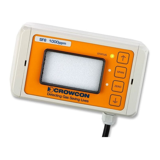
F-Gas Detector Instructions 4. Operating the transmitter using the key-pad The control panel (figure 10) of the transmitter is integrated in the front cover. This is required if zero or span calibration has to be carried out. The following operating and display functions are available: Display elements: STATUS STATUS-LED 3-colours (red, yellow, green) -
Page 12: Regular Operation
4.5. Maintenance Crowcon recommends the detector is zeroed and tested with gas every 12 months as a minimum. The sensor may be zeroed in clean air, and the target gas must be applied at a known concentration to verify correct sensor response. -
Page 13: Exiting Maintenance Mode, Taking Over Changes
F-Gas Detector Instructions The STATUS-LED will then change to signalization, flashing red for 3 seconds and the change to “Regular operation” mode indicated by the STATUS-LED light up green. Generally, maintenance mode will also be exited without taking over any changes if the user has not made any entries for 30 minutes. -
Page 14: Span-Calibration
F-Gas Detector Instructions Keep the ZERO pressed for 3 seconds. Now, the user must apply the correct sample gas for the ZERO-calibration using the available calibration adapter (typically air or nitrogen. In case of doubt, please contact the supplier). If a stable value is found within a time window (60 seconds) regarding the concentration and this value is found in a plausible value range, the ZERO-LED will change from flashing yellow to steady yellow. - Page 15 F-Gas Detector Instructions Now, the user is able to set the desired concentration value of the output signal by using the UP and DOWN keys. For this, the relevant set value can be monitored live at the analogue output. Pressing the UP or DOWN keys for longer will lead to an auto-repeat. This feature is helpful for the adjustment for a larger range.
-
Page 16: Information Sheet, Process Of Operation And Displays
F-Gas Detector Instructions 4.11. Information sheet, process of operation and displays Power STAT STAT STAT M easur e: St ar t up: Failur e: Sensor Out of Sensor Sensor SPAN SPAN SPAN found Range scan br oken ZERO ZERO ZERO Sensor br oken 3 s lat er... -
Page 17: Specifications
F-Gas Detector Instructions 5. Specifications Measuring Principle: Non-dispersive infrared (NDIR) Range: 0-1000ppm Resolution: 1ppm Start-up time: <120 seconds Size: 151 x 80* x 60mm (W x H x D) *Total width with cable gland: 102mm Weight: 0.25Kg Ingress Protection: IP54 Power: 12-28Vdc Analogue Output:... -
Page 18: Product Options
F-Gas Detector Instructions 6. Product options The required gas calibration must be stipulated when ordering a detector. Refer to the labels fixed to the detector to determine the target gas. Pure Fluids: Fluids Formula Name Detector Part Number Exposure Limit Chlorodifluoromethane 1000ppm HCFC 22... -
Page 19: Warranty
(“CRN”). It is essential that the address label is securely attached to the outer packaging of the returned goods. Units returned to Crowcon as faulty and are subsequently found to be ‘fault free’ or requiring service, may be subject to a handling and carriage charge. - Page 20 12 Hongda North Road, Beijing Economic Technological Development Area Beijing, China 100176 Tel: +86 10 6787 0335 Fax: +86 10 6787 4879 Email: saleschina@crowcon.cn Website: www.crowcon.com Crowcon reserves the right to change the design or specification of this product without notice...
Need help?
Do you have a question about the SF6 and is the answer not in the manual?
Questions and answers