Table of Contents
Advertisement
Available languages
Available languages
1 9 . 0 4 - 5 2 9 9 6 6 6 _ 0 3
T r a n s l a t i o n f r o m o r i g i n a l
C K
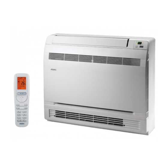
2 6 1 F S - 3 6 1 F S - 5 0 1 F S
I n s t a l l a t i o n m a n u a l
■
MONOSPLIT - CONSOLE
C o o l i n g c a p a c i t y u p 2 , 7 k W t o 5 , 2 k W
H e a t i n g c a p a c i t y u p 2 , 8 k W t o 5 , 3 k W
w w w . a e r m e c . c o m
Advertisement
Table of Contents

Related Manuals for AERMEC CK261FS


Summary of Contents for AERMEC CK261FS
- Page 1 1 9 . 0 4 - 5 2 9 9 6 6 6 _ 0 3 T r a n s l a t i o n f r o m o r i g i n a l 2 6 1 F S - 3 6 1 F S - 5 0 1 F S I n s t a l l a t i o n m a n u a l ■...
- Page 2 Dear customer, Thank you for choosing an AERMEC product. It is the fruit of many years of experience and special design studies and has been made of the highest grade materials and with cutting edge technology. In addition, all our products bear the CE mark indicating that they meet the requirements of the European Machine Directive regarding safety.
-
Page 3: Table Of Contents
INDEX WARNINGS .......................4 AVERTISSEMENTS ....................7 HINWEISE ....................... 10 ADVERTENCIAS ....................13 UNIT TYPE ......................16 CHARACTERISTICS ..................... 16 NOTES ON OPERATION ..................16 ACCESSORIES ....................... 18 TECHNICAL DATA ....................18 NOTES FOR INSTALLATION OF UNIT ............19 DIMENSIONS AND WEIGHTS ................. 21 TECHNICAL DIMENSIONS - JIG KIT .............. -
Page 4: Warnings
1. WARNINGS 1. WARNINGS poisonous, corrosive or hazardous substances. Do not use naked flames near the units. Risk of fire or explosion. Install the unit in a location Split-system air conditioners are designed solely for the with minimal levels of dust, fumes, humidity and purpose of air conditioning indoor rooms of a certain corrosive agents in the air. - Page 5 • This air conditioner must be installed according to • Do not pull or deform the supply cable. If the cable national plant engineering regulations. Particular is pulled or used inappropriately, the unit could be damaged and there is a risk of electric shock. attention must be paid to safety guidelines and •...
- Page 6 • When operating in Cooling mode, the temperature WARNINGS - INDOOR UNIT selected must not be more than 5°C below the outdoor temperature, for optimum comfort and energy saving. • Install the indoor unit and the remote control at least •...
-
Page 7: Avertissements
2. AVERTISSEMENTS 1. AVERTISSEMENTS • Ne pas installer l’unité dans un lieu qui pourrait être soumis à des fuites de gaz inflammable ou de dépôt de matériaux inflammables, explosifs, vénéneux, Les climatiseurs split sont conçus uniquement dans le de substances dangereuses ou corrosives. Ne pas but de climatiser des locaux intérieurs de dimensions et tenir de flammes libres à... - Page 8 uniquement par un « Personnel pourvu des expérience ou sans les connaissances nécessaires, compétences techniques spécifiques ». à condition que ce soit sous surveillance ou bien • Si le câble d’alimentation est endommagé, il doit après que celle-ci ait reçu des instructions relatives à...
- Page 9 des températures élevées et avec les parties en être endommagée et elle peut provoquer des mouvement, comme les ventilateurs. décharges électriques ou des incendies. Contacter le • L’unité extérieure devra être installée de manière Service Après-Vente de la zone. • Ne pas vaporiser de sprays ou d’insecticides sur les à...
-
Page 10: Hinweise
3. HINWEISE 1. HINWEISE • Zur Sicherstellung des ordnungsgemäßen Kondenswasserabflusses müssen die Abflussrohre für das Kondensat richtig installiert werden, anhand Die Split-Klimageräte wurden einzig zum Klimatisieren der Installationsanweisungen. von Innenräumen entwickelt, die mit ihren Maßen und • Das Gerät nicht an einem Ort installieren, wo Gebrauchsbedingungen der installierten Leistung entspre- entzündliches Gas austritt oder sich entzündliches, chen. - Page 11 • Führen Sie nach dem Verlegen der Stromanschlüsse werden, wenn dies unter Aufsicht geschieht oder einen Test durch. Dieser Vorgang darf nur von nachdem diese Personen die angemessenen “Personen mit spezifischer Fachkompetenz” Anweisungen für die sichere Benutzung des Gerätes ausgeführt werden. erlernt und die damit zusammenhängenden •...
- Page 12 • Das Außengerät muss so angebracht werden, dass • Belüftung der Umgebung. Es wird empfohlen, die kein Rückströmen der vom Gerät ausgestoßenen Luft Umgebung, in der das Klimagerät installiert ist, stattfindet und um das Gerät herum ausreichend Platz regelmäßig zu belüften, d.h. besonders dann, wenn für Wartungsarbeiten vorhanden ist.
-
Page 13: Advertencias
4. ADVERTENCIAS 1. ADVERTENCIAS • Para garantizar que el agua de condensación se descargue correctamente, las tuberías de descarga del agua de condensación deben estar Los acondicionadores split han sido diseñados con el correctamente instaladas según las instrucciones de único fin de climatizar locales interiores con dimen- instalación. - Page 14 • No colocar objetos sobre la unidad ni subirse encima. • El aparato puede ser utilizado por niños mayores a 8 Esto podría provocar la caída de los objetos o de las años y personas con capacidades físicas, sensoriales personas con el consiguiente riesgo de lesiones. o mentales reducidas, o sin la experiencia y el •...
- Page 15 • No dejar ningún cable en contacto directo con los • En el caso de anomalías del acondicionador de tubos del refrigerante porque pueden alcanzar aire (por ejemplo, olor a quemado), apagarlo y temperaturas elevadas ni con partes en movimiento desconectar la alimentación eléctrica de la unidad mediante el interruptor omnipolar o el enchufe como los ventiladores.
-
Page 16: Unit Type
5. UNIT TYPE 6. NOTES ON OPERATION 1. NOTES ON OPERATION Indoor units in split-system air conditioners for DEFROSTING THE OUTDOOR UNIT CONSOLE installation are designed to be installed on walls indoors. When the outside temperature is low but there is The air filter is easily accessible to enable regular a high level of humidity, and the unit is operating cleaning. - Page 17 Scanne um das APP zu downloden Escanear para descargar el manual Escanear para descargar el aplicación URL: http://global.ewpeinfo.com/EwpeSmart URL: http://www.aermec.com/qrcode.asp?q=13536 Manuale/Manual/Manuel/Handbuch/Manual Scansiona per scaricare il manuale Scan for download the manual Scan pour télécharger le manuel Scanne um das Handbuch zu downloden...
-
Page 18: Accessories
8. ACCESSORIES CK261FS CK361FS CK501FS WRCA • • • KEY: • Compatible – Not compatible 9. TECHNICAL DATA Indoor unit CK261FS CK361FS CK501FS Monosplit Monosplit Monosplit Compatible system 2,70 Cooling capacity Nominal 0,80 1,20 1,80 Humidity after removal 2,80 3,75... -
Page 19: Notes For Installation Of Unit
INSTALLATION 10. NOTES FOR INSTALLATION OF UNIT 1. NOTES FOR INSTALLATION OF UNIT consequent formation of condensate. Incorrect installation of the pipes can result in water leaks, wetting furniture and other items in the room. WARNINGS CONCERNING INSTALLATION NOISE • The unit and its accessories must only be installed and wired by professionals with the necessary •... - Page 20 with a minimum contact gap of 3mm on both poles. • Check the earth cable is connected to the earthing system of the building itself. • For the power supply, use undamaged cables with a section that is suitable for the load (for information on sections refer to the table provided in this EARTHING: manual).
-
Page 21: Dimensions And Weights
11. DIMENSIONS AND WEIGHTS Without Net weight package (mm) (mm) (mm) (kg) CK261FS 15,5 CK361FS 15,5 CK501FS 15,5 Gross With package (mm) (mm) (mm) weight (kg) CK261FS 18,5 CK361FS 18,5 CK501FS 18,5 Carton Box Example... -
Page 22: Technical Dimensions - Jig Kit
12. TECHNICAL DIMENSIONS - JIG KIT (mm) (mm) (mm) CK261FS CK361FS CK501FS Floor installation Installing semi-recessed Wall mounting (with support) Niche installation... -
Page 23: Minimum Clearances For Indoor Unit
1. MINIMUM CLEARANCES FOR INDOOR UNIT 13. MINIMUM CLEARANCES FOR INDOOR UNIT • Install the unit further than 1m away from other electrical appliances such as TVs, radios, audio equipment, etc. CHOOSING THE INSTALLATION AREA FOR THE • Do not install the unit in a location where it could be INDOOR UNIT affected by inflammable gas leaks. -
Page 24: Installation Of The Indoor Unit
14. INSTALLATION OF THE INDOOR UNIT (4) Remove upper edge To install the unit you must follow the following steps: 1. Open the front panel to access the screws holding the front grille; 2. Remove the 4 screws holding the front grille; 3. - Page 25 1. Choose the mounting position on the wall. 2. Find the points where drill the wall using as a reference the cardboard template supplied. Mark the wall and remove the template ( 3. Choose the screw anchors as a function of the type of wall and of the load which will have to withstand.
- Page 26 POSITION FOR DRILLING HOLES OF SERVICE: Wall SX links DX links Wall SX links DX links DX /SX links Floor Floor Pre-cut side (right and left sides) SELECTION OF AIR DELIVERY This type of unit draws air laterally and enters the environment through two turns distinct, one high and Delivery one low;...
-
Page 27: Fitting The Refrigerant Lines
1. FITTING THE REFRIGERANT LINES 15. FITTING THE REFRIGERANT LINES External Pipe Tightening Pipe thickness Diameter Torque To prepare the copper pipes, proceed as follows: inch (mm) 1. Measure the inner and outer pipe precisely. 1/4˝ (6,35) 0,5-1,0 15~20 2. Use a pipe which is slightly longer than the measurement taken. - Page 28 Fig. A Fig. B Fig. C Fig. D Fig. E Fig. F...
-
Page 29: Condensate Drain
1. CONDENSATE DRAIN 16. CONDENSATE DRAIN • The outlet direction of the condensate discharge hose can be chosen according to the plant requirements of the indoor unit. • The diameter of the condensate discharge hose must be the same as - or greater than - the diameter of the connection pipe. -
Page 30: Electrical Wirings
1. ELECTRICAL WIRINGS 17. ELECTRICAL WIRINGS fans. • Do not modify the circuits inside the air conditioner. The manufacturer cannot be held responsible for • Before carrying out any work, switch off the power any damage or malfunction due to incorrect line supply to the air conditioner. - Page 31 NOTE: • Circuit Breaker and Power Cord Specifications are selected according to the Rated Power Input (Rated Current Input) of the Unit. Rated Power Input (Rated Current Input) is “Maximum” Power Input (“Maximum” Current Input) of the Unit according to EN 60335-1 and EN 60335-2-40.
-
Page 32: Wiring Diagram
18. WIRING DIAGRAM CK261FS - CK361FS - CK501FS WARNING SWITCH ROOM TEMP. TUBE TEMP. RECEIVER AND MOTOR Please don't touch any electronic component or terminal when the SELECT SENSOR SENSOR DISPLAY BOARD machine is running,stopping or has been powered off for less... -
Page 33: Routine Checks Following Installation
1. ROUTINE CHECKS FOLLOWING 19. ROUTINE CHECKS FOLLOWING INSTALLATION INSTALLATION ITEMS TO CHECK POSSIBLE ANOMALY NOTES Is the unit firmly fixed? The unit could fall, vibrate or make noise. Was the unit checked for refrigerant Insufficient output. leaks? Is the thermal insulation sufficient? It could cause condensate and dripping water. -
Page 34: Maintenance
1. MAINTENANCE 20. MAINTENANCE GENERAL NOTES CHECK BEFORE STARTING • Disconnect the power supply before cleaning the • Check to make sure that the inlet and outlet are not unit. obstructed by objects on both units, external and • Disconnect the power supply when the air internal. -
Page 35: Troubleshooting
1. TROUBLESHOOTING 21. TROUBLESHOOTING Anomaly Possible causes The unit cannot be started. • The power supply is not connected. • Check if the power supply cable is damaged. • Check for anomalies on the power supply. • Voltage is too low. The units stops after operating a while. -
Page 36: Error Code List
22. ERROR CODE LIST INDOOR UNIT DISPLAY Display Cooling mode Dehumidification mode Heating mode ON/OFF IR Reciver CODE ALARM DESCRIPTION Circuit failure to control "zero-crossing" Error in jumper cup positioning No signal return from the indoor unit fan Ambient air sensor not connected or short circuit Temperature sensor on the exchanger of the indoor unit not connected or short circuit Temperature sensor on liquid valve not connected or short circuit Temperature sensor on gas valve not connected or short circuit... - Page 37 CODE ALARM DESCRIPTION Drift protection system Protection system for connection sensor Internal communication error Projection system for compressor overheating Internal unit external error recognition (incorrect placement) Internal memory error Wrong connection of the communication cable, or failure of the electronic expansion valve Current control circuit malfunction Wrong connection of the communication cable, or failure of the electronic expansion valve Operating Mode Conflict Error (multisiplt)
- Page 40 DOWNLOAD THE LATEST VERSION: DOWNLOAD THE LATEST VERSION: TÉLÉCHARGER LA DERNIÈRE VERSION: TÉLÉCHARGER LA DERNIÈRE VERSION: http://www.aermec.com/qrcode.asp?q=3983 http://www.aermec.com/qrcode.asp?q=3980 http://www.aermec.com/qrcode.asp?q=3982 A E R M E C S . p . A . V i a R o m a , 9 9 6 - 3 7 0 4 0 B e v i l a c q u a ( V R ) - I t a l y T e l .
Need help?
Do you have a question about the CK261FS and is the answer not in the manual?
Questions and answers