Planet ICA-750 Quick Installation Manual
Dual mode ccd box internet camera
Hide thumbs
Also See for ICA-750:
- Specifications (2 pages) ,
- User manual (54 pages) ,
- Quick installation manual (24 pages)
Advertisement
Quick Links
Advertisement

Related Manuals for Planet ICA-750


Summary of Contents for Planet ICA-750
- Page 1 Dual Mode CCD Box Internet Camera ICA-750 Version 1.0 Quick Installation Guide...
-
Page 2: Table Of Contents
Table of Contents 1. Package Contents ..................3 2. System Requirements ................. 4 3. Outlook...................... 5 3.1 Front Panel ................... 5 3.2 Rear Panel .................... 6 4. Physical Installation ..................7 5. Setup Wizard Configuration ................. 8... -
Page 3: Package Contents
1. Package Contents ● 1 x ICA-750 ● 1 x Camera Stand ● 1 x Power Adapter ● 1 x Allen Wrench ● 2 x Quick Installation Guide ● 1 x CD-ROM Please use the power adapter in this package. Using a power supply with a different voltage rating will damage and void the warranty for this product. Note... -
Page 4: System Requirements
2. System Requirements Network Interface 10/100 Base-TX Ethernet Monitoring System Recommended for Internet Explorer 6.0 or later ● CPU : Pentium 4, 1.5GHz or above ● Memory Size : 512 MB or above ● VGA card resolution : 1024 x 768 or above ● Network bandwidth : In VGA resolu- tion mode, minimum upload bandwidth is System Hardware 1Mbps. Optional : ● Sound Card ● Microphone (for PC) ● Speaker (for PC and ICA-750) -
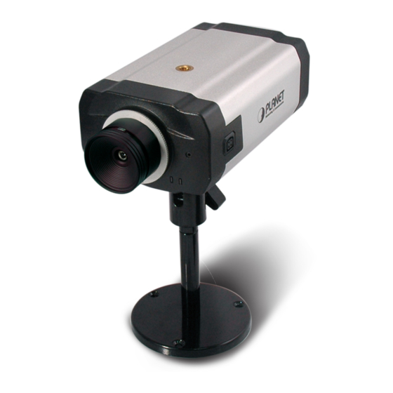
Page 5: Outlook
3. Outlook 3.1 Front Panel Microphone Status LED Description No power. Power on. Blinking The Power LED will blink during start up (15 ~ 20 sec). LAN connection is not detected. LAN connection is detected. Data is being transmitted or received via the LAN Blinking connection. -
Page 6: Rear Panel
3.2 Rear Panel LAN (PoE) Reset AUDIO AUDIO DI / DO I/O Info PORT PORT Description Reset to manufacturer default valued and reboot. When pressed and held over 10 seconds, the settings of IP Reset Camera will be set to the default values. Upon completion, the PWE LED will blink three times. Connect your Camera to a 10/100Base-TX hub or switch. It is LAN (PoE) compliant with IEEE 802.3af standard PoE. Both mid-span & end-span can be used. Connect to the supplied power adapter 12V DC, 1A. When this device is obtaining power from PoE already, you don’t have to attach the power adapter to ICA-750. DI / DO The terminal block includes 2 input ports and 2 output ports. An external microphone can be plugged in. That will disable the AUDIO IN built-in microphone on the front panel. AUDIO OUT An external speaker can be plugged in. -
Page 7: Physical Installation
4. Physical Installation 1. Connect an Ethernet cable Connect one end of an Ethernet cable to the LAN port located on the IP camera’s rear panel and connect the other end to the network device (hub or switch). 2. Attach the external power supply Attach the provided power adapter to the IP camera’s connector labeled “PWR” on the rear panel. 3. Check the LEDs a. The Power LED will turn on briefly, and then start blinking during startup. Af- ter startup is completed, the Power LED will remain ON. b. The LAN LED will be ON. -
Page 8: Setup Wizard Configuration
5. Setup Wizard Configuration Initial setup should be performed by using the supplied Windows-based Setup Wizard as follows: 1. Insert the bundled Product CD into CD-ROM drive to launch the autorun pro- gram. 2. After the web page displayed, click the “Setup Wizard” hyperlink on the menu to start the configuration process. - Page 9 4. After clicking the setup camera button, it will auto search for the IP Cameras on your network. Click on to continue. 5. The next screen below will list the IP Camera on your network. Select it from the list on the left side, the current settings table will be displayed on the right side. Click on to continue.
- Page 10 6. The administrator login window will pop up. If the Administrator Name and Ad- ministrator Password have been set, you will be prompted to enter them. If us- ing the default values, please enter “admin” for both the name and the pass- word. Click on “OK” to continue.
- Page 11 8. You can choose “Fixed IP Address” or “Dynamic IP Address” here. Click on to continue. 1. Fixed IP Address is recommended, and can always be used. 2. Dynamic IP Address can only be used if your LAN has a DCHP Server.DCHP Server. Note 9. If you chose to use Fixed IP Address, the following TCP/IP Settings screen will be displayed. You can configure the IP Address, Subnet Mask, Default Gateway, Primary and secondary DNS. Click on to continue.
- Page 12 10. The next screen below will display all details of the IP Camera. Click on to continue if those settings are correct, or click on back to modify any incor- rect values. 11. In this confirmation window below, click on “OK” to confirm that you want to save the new settings. If you want to cancel your changes, please click on “Cancel”.
- Page 13 12. After confirming, the wizard will start to save the new settings as below screen. 13. When the saving process is completed, the prompt window will be displayed as below screen. Click on “OK” to finish.
- Page 14 14. The setup wizard now is completed. Click on “Exit” to close the setup wizard. After modifications, you may now connect the IP camera with the new configuration via web browser. Further configurations and information can be found in the user’s manual CD. Please check the user’s manual for more understandings.
- Page 15 This page is intentionally left blank...
- Page 16 This page is intentionally left blank...
Need help?
Do you have a question about the ICA-750 and is the answer not in the manual?
Questions and answers