Table of Contents
Advertisement
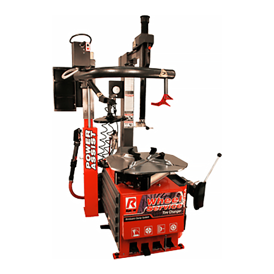
INSTALLATION AND OPERATION MANUAL
TIRE CHANGER
MODELS:
R23LT / R23AT
FOR SERVICING
AUTOMOBILE
AND LIGHT TRUCK
SINGLE PIECE
TIRES/WHEELS
R23LT
SHIPPING DAMAGE CLAIMS
When this equipment is shipped, title passes to the
purchaser upon receipt from the carrier. Consequently,
claims for the material damaged in shipment must be
made by the purchaser against the transportation
company at the time shipment is received.
PLEASE READ THE ENTIRE CONTENTS OF THIS MANUAL PRIOR TO
INSTALLATION AND OPERATION. BY PROCEEDING YOU AGREE THAT YOU
FULLY UNDERSTAND AND
MANUAL. FORWARD THIS MANUAL TO ALL OPERATORS. FAILURE TO OPERATE
THIS EQUIPMENT AS DIRECTED CAN MAY CAUSE INJURY OR DEATH.
COMPREHEND THE FULL CONTENTS OF THIS
Keep this operation manual near the
machine at all times. Make sure that
ALL USERS read this manual.
BE SAFE
Your new Ranger tire changer was designed and
built with safety in mind. However, your overall
safety can be increased by proper training and
thoughtful operation on the part of the operator.
DO NOT operate or repair this equipment without
reading this manual and the important safety
instructions shown inside.
REV C 07-22-11
pn# 5900173
1645 Lemonwood Dr.
Santa Paula, CA. 93060, USA
Toll Free: 1-800-253-2363
Tel: 1-805-933-9970
Fax: 1-805-933-9160
www.rangerproducts.com
Advertisement
Table of Contents

Related Manuals for Ranger Products R23LT


Summary of Contents for Ranger Products R23LT
- Page 1 THIS EQUIPMENT AS DIRECTED CAN MAY CAUSE INJURY OR DEATH. REV C 07-22-11 pn# 5900173 INSTALLATION AND OPERATION MANUAL TIRE CHANGER MODELS: R23LT / R23AT FOR SERVICING AUTOMOBILE AND LIGHT TRUCK SINGLE PIECE TIRES/WHEELS Keep this operation manual near the machine at all times.
-
Page 2: Warranty
R-23LT / 23AT TIRE CHANGER This instruction manual has been prepared especially for you. Your new tire changer is the result of over 25 years of continuous research, testing and development and is the most technically advanced tire changer on the market today. The manner in which you care for and maintain your tire changer will have a direct effect on it’s overall performance and longevity. -
Page 3: Table Of Contents
Section 7: Installation Location ....11 BendPak Inc. / Ranger Products Section 8: Assembly ..... . . 12-14 1645 Lemonwood Dr.,... -
Page 4: Section 1: Definitions Of Hazard Levels
SECTION 1 To maintain machine and user safety, the responsibility of the owner is to read and follow these instructions: DEFINITIONS OF HAZARD LEVELS t Follow all installation instructions. Identify the hazard levels used in this manual with the following definitions and signal words: t Make sure installation conforms to all applicable Local, State, and Federal Codes, Rules, and Regulations;... -
Page 5: Section 2: Safety Instructions
SECTION 2 11. DANGER! The motor on this machine contains high voltage. Disconnect power at the receptacle before performing any IMPORTANT SAFETY INSTRUCTIONS! electrical repairs. Secure plug so that it cannot be accidentally plugged in during service. 12. WARNING! RISK OF EXPLOSION. This Read these safety instructions entirely! equipment has internal arcing or sparking parts which should not be exposed to flam-... -
Page 6: Section 3: Tire And Wheel Service Safety Instructions
SECTION 3 NEVER mount a tire on a damaged or rusty wheel as tire or wheel failure may result during inflation. Explosion from failure may result in severe injury or death of the operator TIRE AND WHEEL SERVICE and bystanders. SAFETY INSTRUCTIONS Inflation ALWAYS be sure the bead opposite the tool is in the drop... -
Page 7: Section 4: Description Of Parts
SECTION 4 Air Inflation Gauge Tower Turbo Blast Tank Bead Breaker Arm Lube Bucket Dispenser Voltage Selector Switch Bead Breaker Shoe Tire Iron Inflation Pedal 10 Turbo Blast Nozzle 11 Helper Disc 12 Tool / Storage Tray 13 Assist Arm Control Pod 14 Horizontal / Vertical Slides 15 Slide Adjustment Handle 16 Left Helper/Restraint Head... -
Page 8: Section 5: Specifications / Tools Required
44" (1118 mm) Shipping Weight R23LT: 712 lbs. (323 Kg) / R23AT: 860 lbs. 391(Kg) Specifications are subject to change without notice. * NOTE: Internal and External Wheel clamping dimensions do not translate directly to rim or tire sizes as Wheel clamping points may vary by manufacturer. -
Page 9: Section 6: Lifting / Uncrating Instructions
Approximate shipping dimensions: (See Fig 6.4) R23LT: 51”W x 44”L x 39”H / 130mm x 112mm x 100mm R23AT: 52W” x 45”L x 73”H/ 132mm x 114mm x 186mm CAUTION! Handling of the machine must be performed only with an appropriate lifting device such as a forklift or pallet jack. - Page 10 While holding the Tilt Tower, carefully cut the Tilt Using a shop crane or fork lift with lifting straps, Tower free of the plastic wrapping securing it to the Tire remove the Tire Changer from the wooden pallet. Use Changer base. only properly rated lifting straps under the Tire Changer base.
-
Page 11: Section 7: Installation Location
SECTION 7 INSTALLATION LOCATION DANGER! These measurements are the tire changer’s working range. Persons other than specially trained and authorized Disconnect tag and lock out power source before operators are expressly forbidden to enter this area. attempting to install, service, relocate or perform any Choose a safe location that is in compliance with maintenance. -
Page 12: Section 8: Assembly
SECTION 8 Fig. 8.4 R23LT ASSEMBLY Tilt Tower 1. Remove the Side Panel. (See Fig. 8.1) Fig. 8.1 5. Remove the Bolts holding the Air Oil Regulator Bracket and set the Air Oil Regulator Assembly aside. (See Fig. 8.5) Fig. 8.5 2. - Page 13 7. Insert the man Pivot Pin though the holes in the Tilt 11. Feed The Tilt Tower Air Line through the hole in the Tower Base and Tilt Tower and secure the Nyloc Nuts. Top of the base Cabinet as shown. (See Fig 8.11) (See Fig.
- Page 14 16. Route the Pressure Gauge Air line through the hole Bead Breaker Blade in the Base Cabinet and connect it to the Pressure Regulator located at the rear of the Cabinet. (See Fig 8.14) 1. Attach the Bead Breaker Blade to the Bead Breaker Arm Assembly.
-
Page 15: Section 9: Anchoring / Air Source/ Oiler Adjustment
SECTION 9 AIR SOURCE This model requires a 14 to 15 CFM air source at 165 PSI ANCHORING maximum pressure. The safe operating pressure range for this model is between 140 PSI and 165 PSI at the machine. A 1/4” ID hose (or pipe) for connection to the machine is It is not essential to anchor the machine to the floor, satisfactory. - Page 16 SECTION 10 NOTE: This adjustment will require two persons to perform. ELECTRICAL SOURCE 2. With the Air source connected, depress the Bead This unit requires power from a 15 amp electrical circuit. Breaker Pedal to operate the Bead Breaker. The unit is supplied standard with a 110 Volt power cord and plug.
-
Page 17: Section 10: Electrical / Wiring Instructions
WIRING INSTRUCTIONS 1. Overheating, short circuits and fire damage will result from inadequate wiring. Wiring must be installed in accordance with National Electric Code and local codes and standards covering electrical apparatus and wiring. 2. Be certain that adequate wire sizes are used, and that: t Service is of adequate amp rating. -
Page 18: Section 11: Operating Instruction
SECTION 11 3. Always loosen the bead on the narrow side of the wheels drop center first. (See Page 19 for better description of the drop center.) OPERATING INSTRUCTIONS 4. Use extra care in positioning the bead breaker shoe on larger wheels/tires, and on alloy wheels. -
Page 19: Important Wheel Mounting Instructions
The following instructions help identify how to properly mount wheels on the tire changer turntable. Failure to follow these instructions may lead to tire and/or wheel damage, equipment damage or failure, serious personal injury or death to operator or bystanders or damage to property. IMPORTANT WHEEL MOUNTING INSTRUCTIONS 1. - Page 20 9. Place tire/wheel assembly on table top with mounting 13. Move the tower forward by depressing the Tower Tilt side up. (See Fig. 11.5) Pedal then press the control button to unlock the horizontal slide. Pull the mount/demount Head forward. (See Fig.
- Page 21 15. Push the locking valve button to lock the slides into 18. Power the left top helper down to force the tire bead into place. As the slides are locked, the mount/demount head the drop the center of the wheel. (See Fig. 11.17 - 11.18) will move upward approximately 1/8 inch and backward Fig.
- Page 22 Fig. 11.22 Fig. 11.26 21. Depress the table top pedal to rotate the wheel clock- 23. Insert the smooth curved end of the tool bar over the wise. Leave the left hand helper in position opposite the right end of demount head and below the lower bead of the demount head and allow it to follow the wheel rotation to tire.
-
Page 23: Section 12: Custom And Special Wheels
DEMOUNTING TUBE TYPE TIRES 1. After both tire beads are loosened, lubricate the beads and rim liberally. 2. Position the demount head and bead lifting tool as described earlier paying careful attention not to pinch the tube. Depress the table top pedal and rotate only a short distance at a time. -
Page 24: Section 13: Mounting
SECTION 13 4. Place tire over wheel and move tower and mount/ demount head into position as described earlier. Position tire so that the lower bead is above the “duckbill” side of the mount/demount head and below the right front knob. (See Fig. -
Page 25: Section 14: Mounting Tube Type Tires
7. With the left side helper, press down on the tire near the right side assist roller to hold the tire in the drop center. (See Fig. 13.8) Fig. 13.8 Fig. 13.12 SECTION 14 8. Depress the table top pedal and rotate the tire until the MOUNTING TUBE TYPE TIRES bead is mounted. -
Page 26: Section 15: Inflation / Inflation Pedal Operation
SECTION 15 INFLATION PEDAL OPERATION INFLATION INSTRUCTIONS The inflation pedal located at the front of the checks air pressure in the tire; controls the flow of air through the inflation hose. (See Fig. 15.1) Tire inflation is performed in four steps: Restraint, Bead Seal, Bead Seat, and Inflation. -
Page 27: Section 16: Stages Of Inflation
SECTION 16 Fig. 16.6 STAGES OF INFLATION Review the following descriptions and diagrams carefully. Refer to them as necessary during wheel restraint, bead sealing, bead seating, and inflation to verify that you are proceeding properly and safely. STAGE TWO / BEAD SEALING WARNING! Remove the Valve Stem Core and position Valve THIS DEVICE ACTS AS A RESTRAINT DEVICE ONLY. - Page 28 TIRE INFLATION WARNING! CHECK THE FUNCTION OF THE PRESSURE LIMITER REGULARLY AND MAINTAIN IT ACCORDING THE INSTRUCTIONS PROVIDED IN THIS MANUAL FOR SAFE AND PROPER OPERATION. DO NOT TAMPER WITH OR ATTEMPT TO ADJUST THE PRESSURE LIMITER. TIRES REQUIRING INFLATION BEYOND 60 PSI SHOULD ONLY BE INFLATED IN A SAFETY CAGE.
-
Page 29: Stage Three: Bead Seating
STAGE THREE / BEAD SEATING Bead seating usually occurs on the long tapered side of the wheel first and the shorter side last. Bead seating WARNING! will usually require at least 7 PSI in the tire. 40 PSI is the maximum safe pressure at this stage regardless of tire operating pressure. -
Page 30: Stage Four: Tire Inflation
STAGE FOUR / TIRE INFLATION 1. Make sure both beads are seated. When both beads are seated, the tire is ready for inflation. WARNING! 2. Replace the valve core if it was removed. CHECK TIRE PRESSURE FREQUENTLY. NEVER 3. Depress the inflation pedal to position two to inflate the EXCEED 40 PSI WHILE SEATING BEADS. -
Page 31: Section 17: Maintenance Instructions
SECTION 17 t Check function of the inflation hose pressure limiter/regulator monthly. Always secure/stow the cover if MAINTENANCE INSTRUCTIONS adjustments are made. The pressure regulator should never be adjusted to exceed 60 PSI. Read and follow all the maintenance instructions provided t The table top, clamps, steel mount/demount head, and in this manual to keep the machine in good operating other working surfaces should be cleaned with a vaporizing... -
Page 32: Water Separator/ Oiler
Mount/Demount Head Cleaning Oiler Adjustment 1. Inspect inserts and clean dirt and debris from the NOTE: mount/demount tool roller with small screw driver or pick. This adjustment will require two persons to perform. (See Fig.17.4) 1. With the Air source connected, depress the Bead Fig. -
Page 33: Turntable Drive Belt
Turntable Drive Belt Inspection / Adjustment. DANGER! The motor on this machine contains high voltage. Disconnect power at the receptacle before performing any electrical repairs. Secure plug so that it cannot be accidentally plugged in during service. 1. Remove the Side Panel. (See Fig. 17.8) Fig. -
Page 34: Inflation Pedal Pressure Limiter Maintenance.34
For additional copies pressure gauge (gauge should read 0). Use a certified tank or further information, contact: with at least 250 PSI pressure rating. (See Fig. 17.9) BendPak Inc. / Ranger Products 1645 Lemonwood Dr., Fig. 17.9 Santa Paula, CA. 93060 1-805-933-9970 www.bendpak.com... - Page 37 DESCRIPTION Bolt M12×70 Chassis body Washer Ø12 Side cover Voltage selector switch & wires BHPS M6X1X12 ZPL Sope brush Washer M6 flat Plastic storage tray Pedal cover Pry bar Metal front cover Washer Ø5 Nut M8 Nut M5 Pedal divider Fitting;...
- Page 39 DESCRIPTION Fitting; 6mm 1/8″straight Prin Ø3X25 Tilt back cylinder Locking valve O-ring spacer; Tilt tower cylinder lower pin 200-1 Tilt cylinder conector O-ring Locking nutM12 200-2 Tilt tower rubber spacer Control valve shaft Tapered metal bushing 200-3 Plastic shock absorber 216-1 Handle W/locking valve Tilt tower pivot pin...
- Page 41 DESCRIPTION Square turntable press pin Square turntable assembly unit Metal Bushing 18X12X11 300-1 Turntable assy Washer 12 Turntable Bolt M12 X 1.75 X 45 Jaw clamp cylinder Square turntable 302-1 Fitting; 1/8" NPT to 8mm Snap ring 65mm 302-2 Small front cylinder cover Washer Ø12 302-3 Y-ring 32X20X6...
- Page 43 DESCRIPTION Quick relief valve BB cylinder Relief valve seal cup Cylinder liner 427-1 Relief valve assembly Nut M18 Bead breaker blade knob Limit stop BB blade stop pin Y-ring Ø200X12×6 Bead breaker bracket BB cylinder piston Bead breaker retaining pin O-ring 193x5.7 Screw M6×25 Eccentric bushing...
- Page 45 DESCRIPTION bearing 80110 Transmission assy Gearbox front flange 500-1 Rotary joint block Screw M8×30 Bolt M10×170 BoltM10X180 HHB M10 X 1.5 X 200 Oil fill tube Washer Ø10 Oil fill tube plug Vertical shaft (short) Y-quick union Bush jack bolt M6×20 Oil block 45×8 O-ring Ø60X2.65 Gear stud...
- Page 47 DESCRIPTION Washer; M6 flat Front foot pedal assy Directional switch bracket Union G1/8″Ø8 Directional switch 1/8" adjustable silencer Directional switch cover Tilt tower air valve Screw M6×55 603-1 Air valve O-ring spacer Foot pedal return spring 603-2 O-ring 17X4 Union G1/8″Ø8 603-3 Air valve spool (all valves) Jaw clamp air valve...
- Page 49 DESCRIPTION Screw M6×20 Support Washer; M6 X 12mm flat Support plate Washer Ø6 Washer Ø8 Self-tapping screw M4X16 Screw M8×20 Turbo blast nozzle adaptor Screw M8×16 730-1 turbo blast complete Washer Ø8 M40 snap ring Washer Ø8 1″connector Washer Ø8 Turbo Blast 1"...
- Page 51 DESCRIPTION Nut M8 Upgrade tower (R-23LT to a R- Assist tower straight arm 23AT) 839-1 Metal braided hose cover L/R assest arm valve cover Slide SHCS M4 X 0.7 X 30mm Assist tower plastic slide Assist arm control valve Slide guide Assist tower bent arm Square tower assy unit 804-1...
- Page 52 For Parts Or Service Contact: BendPak Inc. / Ranger Products 1645 Lemonwood Dr. Santa Paula, CA. 93060 Tel: 1-805-933-9970 Toll Free: 1-800-253-2363 Fax: 1-805-933-9160 www.bendpak.com www.rangerproducts.com pn# 5900173...
Need help?
Do you have a question about the R23LT and is the answer not in the manual?
Questions and answers