Table of Contents
Advertisement
Quick Links
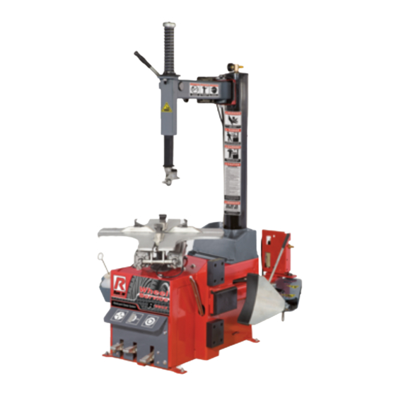
INSTALLATION AND OPERATION MANUAL
MODELS:
R980X
R980X- AT
TIRE CHANGER
FOR SERVICING
AUTOMOBILE
AND LIGHT TRUCk
SINGLE PIECE
TIRES / WHEELS
SHIPPING DAMAGE CLAIMS
When this equipment is shipped, title passes
to the purchaser upon receipt from the carrier.
Consequently, claims for the material damaged in
shipment must be made by the purchaser against
the transportation company at the time shipment is
received.
PLEASE READ THE ENTIRE CONTENTS OF THIS MANUAL PRIOR TO
INSTALLATION AND OPERATION. BY PROCEEDING YOU AGREE THAT
YOU FULLY UNDERSTAND AND COMPREHEND THE FULL CONTENTS OF
THIS MANUAL. FORWARD THIS MANUAL TO ALL OPERATORS. FAILURE TO
OPERATE THIS EqUIPMENT AS DIRECTED MAY CAUSE INjURY OR DEATH.
R980X
R980X-AT
keep this operation manual near the
machine at all times. Make sure that
ALL USERS read this manual.
BE SAFE
Your new Ranger tire changer was designed and
built with safety in mind. However, your overall
safety can be increased by proper training and
thoughtful operation on the part of the operator.
DO
NOT
operate
without
reading
important
safety
instructions
REV D 04-20-11
PN# 5900157
or
repair
this
equipment
this
manual
and
shown
1645 Lemonwood Dr.
Santa Paula, CA. 93060, USA
Toll Free: 1-800-253-2363
Tel: 1-805-933-9970
Fax: 1-805-933-9160
www.rangerproducts.com
the
inside.
Advertisement
Table of Contents

Related Manuals for Ranger Products R980X


Summary of Contents for Ranger Products R980X
- Page 1 THIS MANUAL. FORWARD THIS MANUAL TO ALL OPERATORS. FAILURE TO OPERATE THIS EqUIPMENT AS DIRECTED MAY CAUSE INjURY OR DEATH. REV D 04-20-11 PN# 5900157 INSTALLATION AND OPERATION MANUAL MODELS: R980X R980X- AT TIRE CHANGER FOR SERVICING AUTOMOBILE AND LIGHT TRUCk SINGLE PIECE TIRES / WHEELS...
-
Page 2: Warranty
R980X / R980X-AT Swing-Arm Tire Changer RimGuard This instruction manual has been prepared especially for you. Your new tire changer is the result of over 25 years of continuous research, testing and development and is the most technically advanced tire changer on the market today. -
Page 3: Table Of Contents
Section 7: Installation Location ....11 or further information, contact: Section 8: R980X Assembly ....12-15 BendPak Inc. / Ranger Products Section 9: Anchoring /Air Source/ Oiler Adjustment . -
Page 4: Section 1: Definitions Of Hazard Levels
SECTION 1 OWNER’S RESPONSIBILITY To maintain machine and user safety, the responsibility of DEFINITIONS OF the owner is to read and follow these instructions: HAzARD LEVELS Identify the hazard levels used in this manual with the t Follow all installation instructions. following definitions and signal words: t Make sure installation conforms to all applicable Local, State, and Federal Codes, Rules, and Regulations;... -
Page 5: Section 2: Safety Instructions
SECTION 2 11. DANGER! The motor on this machine contains high voltage. Disconnect power at the receptacle before performing any IMPORTANT SAFETY INSTRUCTIONS! electrical repairs. Secure plug so that it Read these safety instructions entirely! cannot be accidentally plugged in during service. -
Page 6: Section 3: Tire And Wheel Service Safety Instructions
Only properly trained personnel should service tires and inflation gauge and valve. wheels on the R980X/R980X-AT. Read all safety and operating instructions thoroughly before use. The following AlwAys inflate the tire to manufacturer’s recommended safety instructions are for one piece wheels only. -
Page 7: Section 4: Description Of Parts
23. Vertical Shaft Lock Handle 24. Vertical Shaft Spring 25. Voltage Selector Switch (Located on Rear of Cabinet. (See Fig. 4.4) 26. Inflation Pedal (Located on Left of Cabinet. See Fig. 4 .5) R980X-AT Fig. 4.2 Fig. 4.3 Fig. 4.4 Fig. 4.5... -
Page 8: Section 5: Specifications / Tools Required
Maximum Tire Diameter 48" (1219 mm) Shipping Weight R980X:620 lbs. (282 kg)/ R980X-AT 680 lbs. (309kg) Specifications are subject to change without notice. * NOTE: Internal and External Wheel clamping dimensions do not translate directly to rim or tire sizes as Wheel clamping points may vary by manufacturer. -
Page 9: Section 6: Lifting / Uncrating Instructions
SECTION 6 Uncrating Instructions LIFTING/ UNCRATING Carefully cut the plastic wrapping and remove. Carefully cut open the top of the cardboard box. Either 1. The R-980X /AT is shipped on a pallet, Approximate lift off box or cut side panel and remove. shipping dimensions. - Page 10 Remove the four front and rear Bolts and Nuts holding the tire changer from the pallet. (See Figs. 6.8 - 6.9) Fig. 6.6 Fig. 6.8 Fig. 6.9 CAUTION! Handling of the machine must be performed only with an appropriate lifting device such as a forklift or shop crane.
-
Page 11: Section 7: Installation Location
The area selected should be well lit, easy to clean and should be away from oil, grease, brake lathe chips, etc. Avoid areas where bystanders and customers may be present. Machine size is approximately: 36” W x 48” D X 80”H R980X/R980X-AT Fig. 7.1... -
Page 12: Section 8: R980X Assembly
6. Connect the other end of the Air Inflation Hose to the Push to Connect Fitting inside the Air Inflation Box Assembly. (See Fig. 8.4) R980X /AT ASSEMBLY Fig. 8.4 Air Tank/ Tower Assembly 1. Remove the Tool Tray. (See Fig. 8.1) Fig. - Page 13 CAUTION! Keep the Assist Tower Supported by the lifting strap or chain until ALL Assist R980X-AT ASSEMBLY Tower Bracket Bolts have been Tightened. Assist Tower Assembly 4. Using a fork lift or other lifting device, lower the Assist Tower next to the Tower Bracket and align the holes.
- Page 14 tom of the Tank/Tower. (See Fig. 8.10) Fig. 8.13 Install and loosely tighten the Assist Tower Bracket Fig. 8.11 Insert the Top Bracket Bolts that connects the Assist Bolts. (See Fig. 8.11) Fig. 8.14 6. Place the Backing Bracket behind the Tower Bracket and install the Bolts.
-
Page 15: Section 9: Anchoring /Air Source/ Oiler Adjustment
ANCHORING It is not essential to anchor the machine to the floor, CAUTION! however, the floor must be smooth and level. When anchoring to a concrete floor use the mounting holes that are provided in the frame. Make sure the machine is solid Tighten ALL Assist Tower Bracket Bolts and Nuts. - Page 16 SECTION 10 OILER ADJUSTMENT ELECTRICAL SOURCE This unit requires power from a 15 amp electrical circuit. WARNING! The unit is supplied standard with a 110 Volt power cord and plug. (See Fig. 10.1) Failure to properly maintain proper Oil level and adjust the Oil flow may void the warranty Fig.
-
Page 17: Section 10: Electrical / Wiring Instructions
WIRING INSTRUCTIONS 1. Check the voltage, phase and proper amperage requirements for the motor shown on the motor plate. Wiring should be performed by a certified electrician only. 2. Overheating, short circuits and fire damage will result from inadequate wiring. Wiring must be installed in accordance with National Electric Code and local codes and standards covering electrical apparatus and wiring. -
Page 18: Section 11: Operating Instruction
SECTION 11 3. Always loosen the bead on the narrow side of the wheels drop center first. (See Fig. 11.4 and page 18 for better description of the drop center) OPERATING INSTRUCTIONS 4. Use extra care in positioning the bead breaker shoe on larger wheels/tires, and on alloy wheels. -
Page 19: Important Wheel Mounting Instructions
The following instructions help identify how to properly mount wheels on the tire changer turntable. Failure to follow these instructions may lead to tire and/or wheel damage, equipment damage or failure, serious personal injury or death to operator or bystanders or damage to property. IMPORTANT WHEEL MOUNTING INSTRUCTIONS 1. -
Page 20: Wheel Clamp Adjustments
Wheel Clamp Adjustments Fig. 11.8 9. Place the Wheel Protections pads on the Wheel Clamps if desired when clamping from the outside. (See Fig. 11.5) Fig. 11.5 12. Apply tire manufacturer’s approved rubber lubricant liber- ally to entire circumference of both upper and lower beads after loosening bead and placing on table top. - Page 21 14. Push the Vertical Shaft down and position the Mount/ NOTE: Demount Head into contact with the rim edge. (See Fig. This clearance will be maintained as long as the 11.11 - 11.12) Vertical Shaft remains locked. The operator may swing the arm out of the way and back into place again Fig.
- Page 22 19. Insert the smooth curved end of Bead Lifting Tool over the right end knob of the mount/demount head and below the top bead of the tire. (See Fig. 11.16) DANGER! Fig. 11.16 The Bead Lifting Tool and demount head may encounter resistance or come under load at times during the mount and demount procedures.
- Page 23 20. Liberally lubricate the lower bead again, if there was any Fig. 11.24 difficulty lubricating the lower bead earlier. (See Fig. 11.22) Fig. 11.22 Fig. 11.25 21. Lift and hold the tire so it is positioned with the lower bead in the drop-center portion of the wheel. If the tire is large/wide or has become stuck on the lower part of the rim, the Bead Lifting Tool may be used to un-stick and raise the tire.
-
Page 24: Section 12: Custom And Special Wheels
European Performance Wheels (Asymmetrical Hump) Some European wheels have very large humps except near the valve hole. On these wheels, the beads should be loosened at the valve hole on both the upper and lower sides first. Some Wheels with Tire Pressure Warning Sensors Performance wheels on some vehicles have a pressure sensor strapped to the rim opposite the valve hole or mounted on the valve stem. -
Page 25: Section 13: Mounting
SECTION 13 1. Inspect the wheel closely for damage. Clean the wheel and remove any light corrosion or rubber residue. Do not attempt to service heavily corroded wheels. (See Fig. 13.1) MOUNTING Fig. 13.1 This information must be read and followed carefully to prevent accidents and injuries during mounting. - Page 26 4. Place tire over wheel and move Tower and Mount/ Demount Head into position as described earlier. Position tire so that the lower bead is above the left side of the Mount/ Demount Head and below the right front knob. (See Fig.
- Page 27 9. Stand firmly in place and be prepared to hold the Bead 10. With the Drop Center Tool, press down on the tire near Lifting Tool down as the tire/ Turntable rotates. Depress the Mount-demount Head to hold the tire in the drop center. the Table Top Pedal and rotate the tire until the bead is (See Fig.
-
Page 28: Section 14: Mounting Tube Type Tires
SECTION 14 INFLATION PROCEDURES MOUNTING TUBE TYPE TIRES Tire inflation is performed in four steps: Restraint, Bead Seal, Bead Seat, and Inflation. Read the explanation of each step and understand them thoroughly before proceeding. WARNING! Do not force the tire onto the rim. Bead damage could result making the tire unsafe and/or creating the risk of injury. -
Page 29: Section 16: Tire Inflation
TIRE INFLATION of the machine serves two different functions. It checks air pressure in the tire; controls the flow of air through the Inflation Hose. (See Fig. 15.1) The unit is equipped with a Pressure Limiter/Regulator to assist the operator with proper tire inflation. The Pressure Position One - Tire Pressure –... -
Page 30: Stage One: Wheel Restraint R980X Only
STAGE ONE / WHEEL RESTRAINT STAGE TWO / BEAD SEALING (R980X-AT ONLY) As an added safety precaution, a wheel restraint devise has been added to protect operators during tire inflation. WARNING! Operator should keep hands, arms, and entire body away from the tire during the following bead seat and inflation procedures. - Page 31 To seal Low Profile or difficult beads, use the Turbo Blast 3. Position the Turbo-Blast Nozzle to direct air towards the to seal the bead. Rim Center just under the Rim lip. (See Fig. 16.8) CAUTION! NEVER POINT NOzzLE TOWARDS YOURSELF OR OTHER PERSONS.
-
Page 32: Stage Three: Bead Seating
STAGE THREE / BEAD SEATING 1. Once tire pressure is indicated on the air gauge continue Bead seating usually occurs on the long tapered side of to inject air into the tire in short intervals. Check the pressure the wheel first and the shorter side last. Bead seating will frequently. -
Page 33: Stage Four: Inflation
WARNING! Check tire pressure frequently. Never exceed WARNING! 40 PSI while seating beads. Once seated, never THE INFLATION PRESSURE LIMITER IS exceed tire manufacturer’s recommended air PRE-SET AT THE FACTORY AND SHOULD NEED pressure. Tires can explode, especially if they are NO ADJUSTMENT. -
Page 34: Section 17: Maintenance Instructions
SECTION 17 t Check adjustment of the mount/demount head monthly. MAINTENANCE INSTRUCTIONS t Check the condition and adjustment of the turntable drive belt. Read and follow all the maintenance instructions provided t Check function of the Inflation Hose pressure limiter/ in this manual to keep the machine in good operating regulator monthly. -
Page 35: Air Dryer / Oiler
Air Drier /Oiler Maintenance Check oil and water levels regularly, and perform these maintenance items weekly: IMPORTANT! Fig. 17.6 Failure to maintain the Water Separator/ Air Oil regulator in proper condition may void warranty. t Add oil to the lubricator if the fluid level is below the Drain water out of the system regularly middle of the sight glass. -
Page 36: Inflation Pedal Pressure Limiter
Inflation Pedal Pressure Limiter Maintenance Fig. 17.10 WARNING! THE PRESSURE LIMITER IS PRE-SET AT THE FACTORY AND SHOULD NEED NO ADJUSTMENT. ADJUST ONLY IF PRESSURE EXCEEDS 60 PSI. Operating a tire changer with a defective, improperly adjusted, or by-passed pressure limiter could result in a tire explosion with severe injury or death to the operator or bystanders. -
Page 37: Turntable Drive Belt
Turntable Drive Belt Inspection / Adjustment. Inflation Valve Lubrication DANGER! The motor on this machine contains high DANGER! The motor on this machine contains high voltage. Disconnect power at the receptacle before voltage. Disconnect power at the receptacle before performing any electrical repairs. Secure plug so that it performing any electrical repairs. -
Page 38: Transmission Oil Inspection / Lubrication
Transmission Inspection / Lubrication 1. Rotate the Turntable so that the Transmission fill plug is visible. (See Fig. 17.8) DANGER! The motor on this machine contains high voltage. Disconnect power at the receptacle before performing any electrical / repairs. Secure plug so that it cannot be accidentally plugged in during service. - Page 42 R980X-AT Foot Pedal Assembly 22-4 22-3 22-2 22-4 22-3 22-1 22-2 29-1 Product Description Switch arm Complete Pedal Assy Switch bracket Support bracket Switch cover Spring Bead breaker valve Bushing 22.1 Spool valve Pedal 22.2 O-ring Spacer 22.3 Spacer Pedal linkage 22.4...
- Page 43 R980X-AT Vertical Arm Assembly Product Description Roll Pin 6 x 24 Bolt M10 x 25 Bolt M8 x 20 Flat washer Spring Set screw M10 x 16 Plastic handle Set screw M10 x 10 Locking lever Nut M10 Snap ring 42...
- Page 44 R980X-AT Inflation Pedal Assembly 15-1 15-2 15-3 15-4 Product Description qty Pedal Spring Pedal pivot rod Snap ring 12 Pedal linkage Nut M8 Support bracket Regulator Hose fitting Nut M6 Bolt M6 x 20 Hose fitting Hose fitting...
- Page 45 Product Description Hose fitting Bolt M8 x 220 End cap Cylinder Nut M18 Seal Piston Gaskit Bushing Front cap Nut M8 Bushing Seal Lock ring 25 Cylinder rod Seal kit...
- Page 46 15--21 37-39 47-54 1--3 Ref Product Description Screw M4 X50 Bolt M10 X 30 Complete Helper Arm Nut M4 Spacer Base column Washer 10.5 Bolt M12 X 45 Bolt Locking Nut M16 Support plate Nut M10 Washer18 Bolt M10 X 20 Air Cylinder...
- Page 47 17-1 17-2 17-3 17-4 17-12 17-11 17-8 17-5 17-9 17-10 17-6 17-7 17-8 Product Description 17.1 Cylinder Bolt Turntable 17.2 Nut M8 Bolt M12 x 30 17.3 Cylinder tube Turntable cap 17.4 Front cap Clamp 17.5 Rear cap Slide 17.6 Nut M16...
- Page 49 RECORD ALL MAINTENANCE NOTES AND SERVICE HISTORY HERE...
-
Page 50: Maintenance Notes /Tire And Wheel Data
TIRE AND WHEEL DATA... - Page 51 This page intentionally left blank.
- Page 52 For Parts Or Service Contact: BendPak Inc. / Ranger Products 1645 Lemonwood Dr. Santa Paula, CA. 93060 Tel: 1-805-933-9970 Toll Free: 1-800-253-2363 Fax: 1-805-933-9160 www.bendpak.com www.rangerproducts.com PN# 5900157...
Need help?
Do you have a question about the R980X and is the answer not in the manual?
Questions and answers