Table of Contents
Advertisement
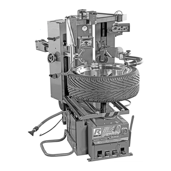
INSTALLATION AND OPERATION MANUAL
TIRE CHANGER
Model RX3040
FOR SERVICING
AUTOMOBILE AND LIGHT
TRUCK SINGLE PIECE
TIRES / WHEELS
SHIPPING DAMAGE CLAIMS
When this equipment is shipped, title passes
to the purchaser upon receipt from the carrier.
Consequently, claims for the material damaged in
shipment must be made by the purchaser against
the transportation company at the time shipment is
received.
PLEASE READ THE ENTIRE CONTENTS OF THIS MANUAL PRIOR TO
INSTALLATION AND OPERATION. BY PROCEEDING YOU AGREE THAT
YOU FULLY UNDERSTAND AND COMPREHEND THE FULL CONTENTS OF
THIS MANUAL. FORWARD THIS MANUAL TO ALL OPERATORS. FAILURE TO
OPERATE THIS EQUIPMENT AS DIRECTED MAY CAUSE INJURY OR DEATH.
Keep this operation manual near the
machine at all times. Make sure that
ALL USERS read this manual.
BE SAFE
Your new Ranger tire changer was designed and
built with safety in mind. However, your overall
safety can be increased by proper training and
thoughtful operation on the part of the operator.
DO
NOT
operate
without
reading
important
safety
instructions
REV A 4-13-10
PN# 5900375
or
repair
this
equipment
this
manual
and
shown
1645 Lemonwood Dr.
Santa Paula, CA. 93060, USA
Toll Free: 1-800-253-2363
Tel: 1-805-933-9970
Fax: 1-805-933-9160
www.rangerproducts.com
the
inside.
Advertisement
Table of Contents

Related Manuals for Ranger Products RX3040


Summary of Contents for Ranger Products RX3040
- Page 1 OPERATE THIS EQUIPMENT AS DIRECTED MAY CAUSE INJURY OR DEATH. REV A 4-13-10 PN# 5900375 INSTALLATION AND OPERATION MANUAL TIRE CHANGER Model RX3040 FOR SERVICING AUTOMOBILE AND LIGHT TRUCK SINGLE PIECE TIRES / WHEELS Keep this operation manual near the machine at all times.
-
Page 2: Warranty
RX3040 TIRE CHANGER This instruction manual has been prepared especially for you. Your new tire changer is the result of over 25 years of continuous research, testing and development and is the most technically advanced tire changer on the market today. -
Page 3: Specifications / Features/ Operator Protective Equipment
10” – 30” / 254 mm - 762 mm or further information, contact: Tire width capacity: 3” - 22” / 76 mm - 559 mm BendPak Inc. / Ranger Products Max tire diameter: 44” / 1118 mm 1645 Lemonwood Dr.,... -
Page 4: Table Of Contents
TABLE OF CONTENTS Page # Warranty ....................................2 Specifications / Features/ Operator Protective Equipment ....................3 Definitions of Hazard Levels ...............................5 INTRODUCTION / OVERVIEW SECTION 1: Definitions of Hazard Levels ........................5 SECTION 2: Owner’s Responsibility ..........................5 SECTION 3: Important Safety Instructions ...........................6 SECTION 4: Tire and Wheel Service Safety Instructions ....................7 SECTION 5:... -
Page 5: Definitions Of Hazard Levels
SECTION 1 SECTION 2 DEFINITION OF HAZARD LEVELS OWNER’S RESPONSIBILITY To maintain machine and user safety, the responsibility of Identify the hazard levels used in this manual with the the owner is to read and follow these instructions: following definitions and signal words: t Follow all installation instructions. -
Page 6: Important Safety Instructions
SECTION 3 11. DANGER! The motor on this machine contains high voltage. Disconnect power at the receptacle before performing any electrical IMPORTANT SAFETY INSTRUCTIONS! repairs. Secure plug so that it cannot be Read these safety instructions entirely! accidentally plugged in during service. 12. -
Page 7: Tire And Wheel Service Safety Instructions
ALWAYS follow all applicable Local, State, and Federal Only properly trained personnel should service tires and Codes, Rules, and Regulations; such as the Federal OSHA wheels on the RX3040. Read all safety and operating Standard Number 1910.177. instructions thoroughly before use. The following safety instructions are for one piece wheels only. -
Page 8: Description Of Parts
SECTION 5 DESCRIPTION OF PARTS (1) Video Monitor — Video assist displays Lower Bead (13) Air Tank — Air storage tank for inflation and “Turbo- Tools. Blast” bead sealing operation. (2) Upper Bead Breaker Roller — Breaks Upper Bead. (14) Camera — Video assist for Lower Bead operations. (3) Control Pod —... - Page 9 (26) Power Center — Houses relays fuses and wiring (38) Thermal Protector — components. (39) Contactor — (27) Power Switch — Powers the Tire Changer On and Off. (40) Timer — (28) Hydraulic Power Unit — Electric motor and pump (41) Fuses —Provides over load protection.
-
Page 10: Assembly Instructions
SECTION 6 Uncrating Instructions ASSEMBLY INSTRUCTIONS Crate Lifting CAUTION! BE CAREFUL WHEN CUTTING BANDING, CLIPS, OR STRAPPING MATERIAL AS ITEMS MAY HAVE BECOME LOOSE AND COULD FALL CAUSING PERSONAL HARM OR INJURY. ALWAYS WEAR DANGER! GLOVES WHEN UNCRATING MACHINE TO PREVENT SCRATCHES, ABRASIONS, OR CUTS HANDLING OF THE MACHINE MUST BE DUE TO CONTACT WITH PACKING MATERIALS. - Page 11 Installation and Assembly CAUTION! KEEP THE ASSIST ARMS STRAPPED TO MACHINE UNTIL AFTER REMOVAL FROM THE DANGER! SHIPPING PALLET. SWINGING ASSIST ARMS DO NOT LIFT OR MOVE UNIT WITHOUT MAY CAUSE DAMAGE OR INJURY. APPROPRIATELY RATED EQUIPMENT. BE SURE THE UNIT IS SECURELY ATTACHED TO ANY 2.
- Page 12 Assembly Fig. 6.8 1. Bolt the Tire Carrier onto the bottom of the Tire Lift. (See Fig. 6.9) Fig. 6.10 2. Remove the tie downs holding the Assist Arms in place. DANGER! FAILURE TO PROPERLY INSTALL THE MACHINE 3. Remove the Quick Nut and Mounting Cones from the CAN LEAD TO IMPROPER AND UNSAFE Center Post.
-
Page 13: Air Source
SECTION 7 AIR SOURCE This model requires a 14 to 15 CFM air source at 45-165 PSI minimum pressure. The safe operating pressure range for this model is between 140 PSI and 165 PSI at the machine. WARNING! CHECK THAT THE TURBO-BLAST VALVE IS CLOSED BEFORE CONNECTING ANY AIR SOURCE. -
Page 14: Electrical Connections
SECTION 8 ELECTRICAL CONNECTIONS Electrical Source DANGER! This unit requires power from a 30 amp electrical THE MOTOR ON THIS MACHINE CONTAINS circuit. Standard wiring is 208-230V/60hz/Single Phase. HIGH VOLTAGE. DISCONNECT POWER AT THE RECEPTACLE BEFORE PERFORMING ANY Refer to the serial tag of the machine for specific ELECTRICAL REPAIRS. - Page 15 WIRING INSTRUCTIONS 1. Check the voltage, phase and proper amperage requirements for the motor shown on the motor plate. Wiring should be performed by a certified electrician only. 2. Overheating, short circuits and fire damage will result from inadequate wiring. Wiring must be installed in accordance with National Electric Code and local codes and standards covering electrical apparatus and wiring.
-
Page 16: Control Overview
SECTION 9 Wheel Lift CONTROL OVERVIEW Raises and lowers wheel and tire up to and off the Center Post. (See Fig. 9.2) Fig. 9.2 CAUTION! THE UNIT MUST BE PROPERLY OPERATED AND MAINTAINED TO HELP AVOID ACCIDENTS THAT COULD DAMAGE THE UNIT AND INJURE THE OPERATOR OR BYSTANDERS. - Page 17 Center Post Fig. 9.6 CENTER POST - HEIGHT ADJUSTMENT 1. The Center Post has two Height position. High and Low. 2. To adjust the Center Post remove the Hair Pin and Shaft pin and raise or lower the Center Post as required. (See Fig.
- Page 18 Turntable Fig. 9.9 1. The Turntable rotates clock wise and counter clockwise and is controlled by the Turntable Rotation Pedal. NOTE: Table top rotation can be stopped at any time by removing your foot from the rotation pedal. Normal table top rotation for demounting is clockwise. Depress the table top pedal to rotate this direction.
- Page 19 Bead Breaker Rollers 2. Both the Upper and Lower Bead Breaker Rollers height is adjustable using the Control Pod. (See Fig. 9.12 - 9.13) Both the upper and lower Bead Breaker Rollers are adjustable. Fig. 9.12 1. To adjust the length of the Bead Breaker rollers, remove the Hair Pin and Bead Breaker Lock Pin.
- Page 20 Top Bead Assist Roller 3. When the Upper Bead Breaker Roller is raised to the Highest position the Upper Bead Breaker Roller Arm Automatically flips up and out of the way. (See Fig. 9.14) 1. The top Bead Assist Roller helps position the top bead into the drop Center of the Wheel during mounting and demounting.
- Page 21 Tool Head IN AND OUT- MANUALLY 1. Using the Joystick on the Control Pod to Retract and Extend the Tool Head Assembly In or Out. (See Fig. 9.20) There are two options for the Tool head. Steel and Plastic. The Tool Head can be adjusted in 4 ways. 1.
- Page 22 IN AND OUT- AUTO LOCATING- TARGET LOCK™ HOOK OR TAB POSITION Exclusive to the Ranger RX3040 is the Target Lock™ The orientation of the Tool Head can be changed to feature. Once the Position of the Bead Breaker Rollers select either the Hook or Tab end up. Hook end is used are located in relation to the Rim edge.
- Page 23 Assist Tools 2. To Operate the Drop Center Tool. Push Up on the Joystick to move the Drop Center Tool up and press down to move the Drop Center Tool down. (See Fig. 9.28) REVERSIBLE DROP CENTER TOOL 1. The Reversible Drop Center Tool is adjustable manually and operated pneumatically using the Joystick mounted on the Drop Center Arm.
- Page 24 2. Lifting or supporting the under side of the tire to help Center the Lower Bead into the Drop Center of the Rim when Mounting. (See Fig. 9.30) Fig. 9.30...
- Page 25 Turbo-Blast Nozzle 1. To Open the Slide Valve, PUSH the Slide Valve Forward. The Turbo-Blast Nozzle provides a powerful burst of 2. To Close PULL the Slide Valve closed. air to seat the Tire Bead. (See Fig. 9.32) 1. The Turbo-Blast Nozzle can be stored on the Hook at Fig.
- Page 26 Air /Oil Regulator / Dryer Assembly 2. To activate the Inflation hose. Step on the Inflation Pedal. (See Fig. 9.34) The Air Oil Regulator regulates the incoming pressure and, removes moisture from incoming air, and oils the air that is sent to the Pneumatic Cylinders. 1.
- Page 27 5. Adjust the oil flow so that two to three drops are visible through the Oil Flow Site Glass when operating the Wheel Lift. Water Reservoir CAUTION! NOTE! THE AIR SUPPLY MUST BE DISCONNECTED PRIOR TO FILLING THE OIL RESERVOIR. THE AIR SUPPLY SHOULD BE CONNECTED WHEN DRAINING THE WATER RESERVOIR.
- Page 28 Air Tank Monitor 1. The Air Tank has a separate Pressure Regulator and 1. The Video Monitor will come on when the machine is Gauge. Located on the top of the Tank. (See Fig. 9.41) power up. Check that the Power button is on, if Monitor fails to display an image.
- Page 29 Fig. 9.47 Fig. 9.48...
-
Page 30: Wheel Inspection And Prep
OPERATIONS SECTION 10 Wheel Inspection u Remember to remove all weight from both sides of the WHEEL INSPECTION and wheel. On alloy wheels, always rotate the wheel on turn MACHINE PREPARATION after setting the head to insure proper wheel chucking. u Review the performance wheel section of this manual prior to servicing performance tire/wheel combinations. - Page 31 The following instructions help identify how to properly mount wheels on the tire changer turntable. Failure to follow these instructions may lead to tire and/or wheel damage, equipment damage or failure, serious personal injury or death to operator or bystanders or damage to property. IMPORTANT WHEEL MOUNTING INSTRUCTIONS 1.
- Page 32 CAUTION! CHECK THAT NO TOOLS, OBJECTS OR PEOPLE ARE IN THE WAY OF THE MOVING COMPONENTS OF THE MACHINE Before loading a tire onto the RX3040, prepare the machine. 1. Move the upper Bead Breaker Roller to its highest position.
-
Page 33: Demounting A Tire
SECTION 11 Fig. 11.3 DEMOUNTING A TIRE Roll the tire onto the Wheel Lift. (See Fig. 11.1) Fig. 11.1 Center the tire rim over Turntable post. Press the Wheel Lift Pedal again to lower the rim onto Turntable. Align a lug hole on the rim towards the front of the machine (at 6 o’clock position). - Page 34 11. Flip Down the Upper Bead Breaker Roller. (See Fig. 11.8) Fig. 11.8 CAUTION! DAMAGE CAUSED BY STRIKING OR HITTING THE QUICK-NUT WITH A HAMMER, TIRE IRON OR HEAVY OBJECT IS NOT COVERED UNDER WARRANTY! 11. Place the Quick Nut over the Post spin and hand tighten the Quicken Nut.
- Page 35 Fig. 11.11 Fig. 11.14 WARNING! NOTE! KEEP HANDS CLEAR! KEEP HANDS CLEAR OF ALL COMPONENTS THE LOWER BEAD BREAKER ROLLER IS SET TO OF THE TIRE CHANGER WHEN ROTATING BE THE SAME DISTANCE FROM THE RIM AS THE TURNTABLE DURING MOUNTING PROCEDURES. UPPER BEAD BREAKER ROLLER.
- Page 36 17. Pulse the Upper Bead Breaker switch down in small Fig. 11.18 increments and the Lower Bead Breaker control up as the tire rotates to begin to break both the Upper and Lower Beads. 18. Stop the rotation of the Turntable. 19.
- Page 37 27. Using the Tool Head Control, lower the Tool Head down to just above the rim. (See Fig. 11.24) WARNING! ALWAYS USE A LIBERAL AMOUNT OF TIRE MANUFACTURE’S RECOMMENDED LUBRICANT. FAILURE TO DO SO CAN DAMAGE THE TIRE, RIM OR THE ELECTRIC MOTOR AND MAY VOID THE WARRANTY.
- Page 38 29. Depress the Turntable Rotation Pedal. 32. Continue rotating the tire and Pull Bead out. (See Fig. 11.27) (See Fig. 11.30) Fig. 11.27 Fig. 11.30 33. Continue Pulling the Bead up . . . and then in. (See Fig. 11.31) WARNING! ALWAYS USE A LIBERAL AMOUNT OF TIRE MANUFACTURE’S RECOMMENDED LUBRICANT.
- Page 39 Removing Lower Bead 7. Use the video assist feature to guide the Tool Head Tab under the tire’s lower Bead. (See Fig. 11.36 - 11.37) Move the Tool Head up and retract the Tool Head in. Fig. 11.36 The Tool Head should be with the Tab positioned up. With the Tool Head fully retracted, move the Tool Head Assembly down to it’s lowest position.
- Page 40 WARNING! KEEP HANDS CLEAR! KEEP HANDS CLEAR OF ALL COMPONENTS OF THE TIRE CHANGER WHEN ROTATING TURNTABLE DURING MOUNTING PROCEDURES. THERE ARE MANY PINCH OR CRUSH HAZARDS IF HANDS ARE KEPT IN CONTACT WITH THE MACHINE DURING DEMOUNTING ROTATION. NOTE: TABLE TOP ROTATION CAN BE STOPPED AT ANY TIME BY REMOVING YOUR FOOT FROM THE ROTATION PEDAL.
-
Page 41: Section 12: Custom And Special Wheels
SECTION 12 SECTION 13 CUSTOM AND SPECIAL WHEELS DEMOUNTING TUBE TYPE TIRES 1. After both tire beads are loosened, lubricate the beads and rim liberally. DANGER! NOTE: IF A CUSTOM WHEEL IS DAMAGE DURING TABLE TOP ROTATION CAN BE STOPPED AT DISMOUNTING, STOP AND AVOID DAMAGING ANY TIME BY REMOVING YOUR FOOT FROM THE THE OTHER WHEEL. -
Page 42: Section 14: Mounting A Tire
SECTION 14 Inspect the wheel closely for damage. Clean the wheel and remove any light corrosion or rubber residue. MOUNTING A TIRE Do not attempt to service heavily corroded wheels. (See Fig. 14.1) WARNING! CHECK TIRE AND WHEEL CAREFULLY BEFORE MOUNTING. MAKE SURE THE TIRE BEAD DIAMETER AND WHEEL DIAMETER MATCH EXACTLY. - Page 43 Lower Bead Seating Upper Bead Seating Lower the Tool Head with the Tab side down to bring Before performing the mounting procedure, prepare the the upper bead below the upper rim edge. (See Fig. 14.6) machine. 1. Move the Upper Bead Breaker Roller to its highest position.
- Page 44 Lower the Drop Center Tool to Push the Upper Bead Press the Turn table Rotation pedal to rotate the tire below the Rim’s Drop Center. (See Fig. 14.9) and rim clockwise. KEEP HANDS CLEAR! (See Fig. 14.10) Fig. 14.10 Continue rotation till Upper Bead drops below Rim. Fig.
-
Page 45: Mounting Tube Type Tires
SECTION 15 MOUNTING TUBE TYPE TIRES 1. Lubricate the beads and rim liberally. 2. Mount the lower Bead as indicated in Section 14. 3. Round out the tube with a small amount of air. Avoid pinching or forcing the tube. Apply rubber lubricant to the tube. -
Page 46: Inflation Instructions
SECTION 16 INFLATION PEDAL OPERATION INFLATION INSTRUCTIONS The inflation pedal located at the front of the checks air pressure in the tire; controls the flow of air through the inflation hose. (See Fig. 16.1) Tire inflation is performed in four steps: Restraint, Bead Seal, Bead Seat, and Inflation. - Page 47 STAGES OF INFLATION Review the following descriptions and diagrams carefully. Refer to them as necessary during wheel restraint, bead sealing, bead seating, and inflation to verify that you are proceeding properly and safely. Fig. 16.5 WARNING! Hold tire up against upper edge of the wheel. Be sure tires top bead is over the bottom of the valve stem.
- Page 48 TIRE INFLATION Position the Turbo-Blast Nozzle to direct air towards the Rim Center just under the Rim lip. (See Fig. 16.7) Fig. 16.7 WARNING! CHECK THE FUNCTION OF THE PRESSURE LIMITER REGULARLY AND MAINTAIN IT ACCORDING THE INSTRUCTIONS PROVIDED IN THIS MANUAL FOR SAFE AND PROPER OPERATION.
- Page 49 STAGE THREE / BEAD SEATING Bead seating usually occurs on the long tapered side WARNING! of the wheel first and the shorter side last. Bead seating will usually require at least 7 PSI in the tire. 40 PSI is the maximum safe pressure at this stage regardless of tire KEEP HAND AND FINGERS CLEAR! operating pressure.
- Page 50 WARNING! CHECK TIRE PRESSURE FREQUENTLY. NEVER EXCEED 40 PSI WHILE SEATING BEADS. ONCE SEATED, NEVER EXCEED TIRE MANUFACTURER’S RECOMMENDED AIR PRESSURE. TIRES CAN EXPLODE, ESPECIALLY IF THEY ARE INFLATED BEYOND THEIR LIMITS. AT ALL PRESSURE LEVELS, WHEN INFLATING THROUGH THE VALVE STEM;...
- Page 51 STAGE FOUR / TIRE INFLATION 1. Make sure both beads are seated. When both beads are seated, the tire is ready for inflation. DANGER! 2. Replace the valve core if it was removed. IMPORTANT! 3. Depress the inflation pedal to inflate the tire. WHEN INFLATING TIRES THAT REQUIRE MORE DO NOT STAND OVER TIRE DURING INFLATION.
-
Page 52: Maintenance Instructions
SECTION 17 t Check for worn, damaged or missing parts including grips and protective covers. Replace them before allowing MAINTENANCE INSTRUCTIONS the unit to be used. t Check the tire pressure gauge function daily, and check. Read and follow all the maintenance instructions provided in this manual to keep the machine in good operating t On a daily basis, inspect the unit and check to be condition. - Page 53 t The vertical and horizontal slides and the helper slides t The table top, steel Tool Head, and other working should be cleaned with a vaporizing solvent and then surfaces should be cleaned with a vaporizing solvent every lubricated with chassis grease once a month. month.
- Page 54 ADJUSTMENT OF TOOL HEAD Fig. 17.5 TARGET LOCK™ LIMIT SWITCH 1. Mount an empty rim onto the turntable. CAUTION! ANY TIME THE TOOL HEAD IS CHANGED FROM THE STEEL HEAD TO PLASTIC OR VICE VERSA, THE STOP POSITION OF THE TOOL HEAD MUST BE ADJUSTED.
- Page 55 7. The Limit switch is located under the Tool Head 11. Lower the Tool Head to gauge the distance from the Sliding Arm. Tab Side of the Tool Head to the Lower Rim Edge. (See Fig. 17.8) 8. Loosen the Socket Head Cap screws and move the switch assembly forward or rearward as required.
- Page 56 INFLATION PEDAL PRESSURE LIMITER 3. Depress inflation pedal to start air flow through the hose MAINTENANCE and into the tank. Maintain a steady pressure for constant flow. 4. Watch the rising pressure on the tank gauge and the gauge on the machine. As tank pressure reaches 60 PSI, the pressure limiter should stop the air flow automatically.
- Page 57 DRIVE BELT ADJUSTMENT 1. Remove right side access panel. 2. Inspect the Drive Belt for cracking and wear and replace as necessary. Adjust the Belt deflection to 3/8” - 1/2”. (See Fig. 17.12) Fig. 17.12...
-
Page 58: Critical Safety Warnings
CRITICAL SAFETY WARNINGS... - Page 59 CRITICAL SAFETY WARNINGS...
-
Page 60: Features / Specifications
FEATURES / SPECIFICATIONS MODEL RX3040 ype of Drive System Air / Electric-Hydraulic Dual Motors* 2 & 3 Hp / 208-230V 60HZ 1 Ph Air Requirement 140-165 psi (10-11 bar) Wheel Clamping Method Threaded Shaft / Cones / Quick-Nut Wheel Clamping Capacity 10”-30”... -
Page 61: Parts Breakdowns
Parts Breakdowns... - Page 70 T I R E C H A N G E R X. Electric Schematic Diagrams - 12 -...
- Page 71 T I R E C H A N G E R All electric appliances must be installed by electricians. - - 13 -...
- Page 72 T I R E C H A N G E R XI. Air Circuit Schematic Diagram 1.Pressure regulating valve 2.Pressure gauge 3.Oil-water separator 4.Muffler 5. Tire carrier valve under three-position five-way control 6. Rotary valve of working head under three-position five-way control 7.
- Page 73 T I R E C H A N G E R XII. Oil Circuit Schematic Diagram 1. Filter screen 2.Gear pump 3.Overflow valve 4.One-way valve 5. Tire shovel wheel cylinder under 4/3 electromagnetic control 6. Tire shovel wheel cylinder under 4/3 electromagnetic control 7.
- Page 74 For Parts Or Service Contact: BendPak Inc. / Ranger Products 1645 Lemonwood Dr. Santa Paula, CA. 93060 Tel: 1-805-933-9970 Toll Free: 1-800-253-2363 Fax: 1-805-933-9160 www.bendpak.com www.rangerproducts.com PN# 5900375...
Need help?
Do you have a question about the RX3040 and is the answer not in the manual?
Questions and answers