Table of Contents
Advertisement
WARNING
!
INSTALLATION AND OPERATION MANUAL
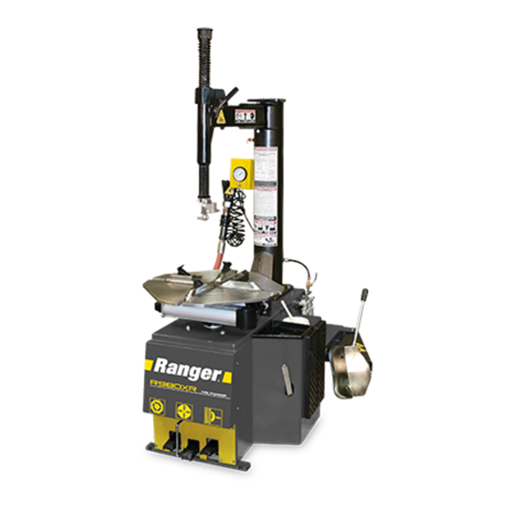
MODELS:
• R980AT
• R980XR
RECEIVING
The shipment should be thoroughly inspected as soon as it
is received. The signed Bill of Lading is acknowledgement
by the shipping carrier as receipt of this product as listed
in your invoice as being in a good condition of shipment. If
any of these goods listed on this Bill of Lading are missing
or damaged, do not accept goods until the shipping carrier
makes a notation on the freight bill of the missing or dam-
aged goods. Do this for your own protection.
PLEASE READ THE ENTIRE CONTENTS OF THIS MANUAL PRIOR TO INSTALLATION
AND OPERATION. BY PROCEEDING WITH TIRE CHANGER INSTALLATION AND
OPERATION YOU AGREE THAT YOU FULLY UNDERSTAND AND COMPREHEND
THE FULL CONTENTS OF THIS MANUAL. FORWARD THIS MANUAL TO ALL
OPERATORS. FAILURE TO OPERATE THIS EQUIPMENT AS DIRECTED MAY CAUSE
INJURY OR DEATH.
R980AT
IMPORTANT SAFETY INSTRUCTIONS
SAVE THESE INSTRUCTIONS
BE SAFE
Your new tire changer was designed and built with safety
in mind. However, your overall safety can be increased with
proper training and thoughtful operation on the part of the
operator. DO NOT operate or repair this equipment without
reading this manual and the important safety instructions
shown inside. Keep this operation manual near the tire
changer at all times. Make sure that ALL USERS read and
understand this manual.
1
Revision D - Sept. 2019
R980XR
1645 Lemonwood Dr.
Santa Paula, CA. 93060, USA
Toll Free 1-800-253-2363
Tel: 1-805-933-9970
Fax: 1-805-933-9160
www.bendpak.com
P/N 5900158
Advertisement
Chapters
Table of Contents

Related Manuals for Ranger Products R980AT


Summary of Contents for Ranger Products R980AT
- Page 1 OPERATORS. FAILURE TO OPERATE THIS EQUIPMENT AS DIRECTED MAY CAUSE INJURY OR DEATH. Revision D - Sept. 2019 P/N 5900158 INSTALLATION AND OPERATION MANUAL MODELS: • R980AT • R980XR R980AT R980XR RECEIVING BE SAFE The shipment should be thoroughly inspected as soon as it Your new tire changer was designed and built with safety is received.
-
Page 2: Warranty
RANGER R980 SERIES This instruction manual has been prepared specifically for you. Your new Ranger Tire Changer is the product of over 40 years of continuing research, testing and development; it is the most technically advanced tire changer on the market today. -
Page 3: Section 1: Owner's Responsibility
BEFORE YOU BEGIN DEFINITIONS OF HAZARD LEVELS NOTIFY THE CARRIER AT ONCE if any hidden loss or damage is discovered after receipt and request the carrier Identify the hazard levels used in this manual with the to make an inspection. If the carrier will not do so, prepare following definitions and signal words: a signed statement to the effect that you have notified the carrier (on a specific date) and that the carrier has failed to... -
Page 4: Table Of Contents
TABLE OF CONTENTS Warranty......... . 2 Section 1: Owner’s Responsibility . -
Page 5: Section 2: Safety Instructions
IMPORTANT SAFETY INSTRUCTIONS SECTION 2- IMPORTANT SAFETY INSTRUCTIONS Read these safety instructions entirely. Do not attempt to install this machine if you have never been trained on basic garage equipment installation procedures. Never attempt to lift components without proper lifting tools such as forklifts or cranes. -
Page 6: Section 3: Tire And Wheel Service Safety Instructions
SECTION 3 INFLATION TIRE AND WHEEL SERVICE ALWAYS be sure the bead opposite the tool is in the drop SAFETY INSTRUCTIONS center before rotating the tire when demounting or mounting to avoid damage to the tire beads. ALWAYS follow all applicable Local, State, and Federal Codes, Rules, and Regulations;... -
Page 7: Section 4: Description Of Parts
SECTION 4 - DESCRIPTION OF PARTS - R980XR Tank Pressure Relief Valve Tower (Air Tank) Tool Tray Air Drier / Oiler (See Fig 4.2) Bead Breaker Arm Bead Breaker Blade Bead Breaker Pad Bead Lifting Tool Turntable Foot Pedal (See Fig 4.3) 10. -
Page 8: Section 4: Description Of Parts
SECTION 4 - DESCRIPTION OF PARTS - R980AT Tank Pressure Relief Valve Tower (Air Tank) Tool Tray Air Drier / Oiler (See Fig 4.2) Bead Breaker Arm Bead Breaker Blade Bead Breaker Pad Bead Lifting Tool Turntable Foot Pedal 10. Bead Breaker Foot Pedal 11. -
Page 9: Section 5: Specifications / Tools Required
SECTION 5 - SPECIFICATIONS AND FEATURES Specification R980AT R980XR Motor 3 HP (220 VAC 50-60 HZ) 3 HP (220 VAC 50-60 HZ) Drive System Type Electric / Air Electric / Air Air Requirement 140-165 PSI (10-11 BAR) 140-165 PSI (10-11 BAR) -
Page 10: Section 6: Lifting / Un-Crating Instructions
SECTION 6 UN-CRATING INSTRUCTIONS LIFTING/ UN-CRATING Using a crow bar or pry bar, locate the metal tabs and pry open the tabs and or staples. (See Fig 6.3) 1. The unit is shipped on a pallet. Approximate shipping dimensions are shown below. (See Fig 6.1) Fig 6.3 Fig 6.1 The entire wooden frame/box can be lifted off after... - Page 11 Fig 6.6 Fig 6.8 HANDLING OF THE MACHINE MUST BE PERFORMED ONLY WITH AN APPROPRIATE LIFTING DEVICE SUCH AS A FORKLIFT OR SHOP CRANE. ONLY PERSONNEL WHO ARE EXPERIENCED AND QUALIFIED ON MATERIAL HANDLING PROCEDURES SHOULD HANDLE ANY TRANSPORTATION OR MOVING OF MACHINE. Fig 6.9 SECURE THE AIR TANK / ASSIST TOWER WITH SHOP CRANE/FORKLIFT OR PERSONNEL PRIOR TO...
-
Page 12: Section 7: Installation Location
INSTALLATION ALSO HELPS PROTECT THE UNIT FROM DAMAGE AND MAKES SERVICE EASIER. ALWAYS KEEP THIS MANUAL WITH UNIT. R980XR size is approximately: 43” W x 51” D X 80”H R980AT size is approximately: 51” W x 45” D X 73”H R980AT 73” 51”... -
Page 13: Section 8: Assembly/ Anchoring
SECTION 8 Fig 8.3 Socket Head AIR TANK/ TOWER ASSEMBLY Cap Screw 1. Using a fork lift or other lifting device, lower the Tank/ Tower onto the base and align the holes. Locking 2. Attach the Tank / Tower assembly to the Base using the Handle four bolts on the Tower Base Plate. -
Page 14: Section 9: Air Source/ Oiler Adjustment
3. Observe the sight glass and adjust the oil flow of the SECTION 9 oiler by turning the Oiler Adjustment Screw by using a small AIR SOURCE screwdriver so that 2-3 drops of oil drip through the sight glass for each operation of the Bead Breaker Pedal. (See This model requires a 14 to 15 CFM air source at 175 PSI maximum pressure. -
Page 15: Section 10: Electrical / Wiring Instructions
THIS EQUIPMENT MUST BE GROUNDED WHILE IN USE TO PROTECT THE OPERATOR FROM ELECTRIC SHOCK. NEVER CONNECT THE GREEN POWER CORD WIRE TO A LIVE TERMINAL. THIS IS FOR GROUND ONLY. THE MOTOR ON THIS MACHINE CONTAINS HIGH VOLTAGE. DISCONNECT POWER AT THE RECEPTACLE BEFORE PERFORMING ANY ELECTRICAL REPAIRS. -
Page 16: Bead Loosening
the wheel to be clamped un-level. This may result in the breaker pedal to actuate the blade and loosen the bead. It combination mount/demount head contacting the rim causing may be necessary to loosen the bead in multiple locations scratches. On alloy wheels, always rotate the wheel one turn around the tire. -
Page 17: Important Wheel Mounting Instructions
Fig 11.5... -
Page 18: Wheel Clamp Adjustments
WHEEL CLAMPING DEMOUNTING 1. Place the Wheel Protector pads on the Wheel Clamps if 1. Apply tire manufacturer’s approved rubber lubricant desired when clamping from the outside. (See Fig 11.6) liberally to entire circumference of both upper and lower beads after loosening bead and placing on table top. (See Fig 11.6 Fig 11.9) Fig 11.9... - Page 19 Fig 11.11 Fig 11.13 THE BEAD LIFTING TOOL AND DEMOUNT HEAD MAY ENCOUNTER RESISTANCE OR COME UNDER LOAD AT TIMES DURING THE MOUNT AND DEMOUNT PROCEDURES. KEEP ONE HAND FIRMLY ON THE TOOL TO AVOID POSSIBLE TOOL KICK BACK. USE THE REVERSING FEATURE (LIFT TABLE TOP PEDAL UPWARDS) TO BACK OUT OF JAM UPS.
- Page 20 9. Push the Bead Lifting Tool down toward the wheel to lift Fig 11.20 the tire bead up and over the tab of the demount head. Hold the Bead Lifting Tool in this position. (See Fig 11.16) Fig 11.16 12. Liberally lubricate the lower bead again, if there was any difficulty lubricating the lower bead earlier.
-
Page 21: Section 12: Custom And Special Wheels
15. Depress the Table Top Pedal to rotate the wheel. SECTION 12 CUSTOM AND SPECIAL WHEELS 16. The Mount / Demount Head will guide the bead up and over the edge of the wheel. Continue rotation until the lower bead is demounted. (See Fig 11.24 -11.26) IF A CUSTOM WHEEL IS DAMAGED WHILE DEMOUNTING, STOP, AND AVOID DAMAGING THE OTHER WHEELS. -
Page 22: Demounting Tube Tires
DEMOUNTING TUBE TYPE TIRES 3. Lubricate both tire beads liberally with tire manufacturer’s approved lubricant. (See Fig 13.3) 1. After both tire beads are loosened, try to remove the Fig 13.3 tube. If you can not remove the tube lubricate the beads and rim liberally. - Page 23 Fig 13.5 NEVER MOUNT A TIRE AND WHEEL HANDED TO YOU BY ANYONE WITHOUT CHECKING BOTH TIRE AND WHEEL FOR DAMAGE AND COMPATIBILITY. BE EXTRA CAUTIOUS OF PERSONS WITHOUT KNOWL- EDGE OF TIRE SERVICE. KEEP BYSTANDERS OUT OF SERVICE AREA. Fig 13.6 NEVER MOUNT A DAMAGED TIRE.
- Page 24 8. Stand firmly in place and be prepared to hold the Bead Fig. 13.12 Lifting Tool down as the tire/ Turntable rotates. Depress the Table Top Pedal and rotate the tire until the bead is mounted. (See Fig. 13.9 - 13.12) Fig.
-
Page 25: Mounting Tube Tires
SECTION 14 Fig 13.15 INFLATION The Inflation Pedal located at the center of the left side of the machine serves two different functions. It checks air pressure in the tire and controls the flow of air through the Inflation Hose. (See Fig 14.1) Fig 14.1 Inflation Pedal Fig 13.16... - Page 26 TIRE FAILURE UNDER PRESSURE IS HAZARDOUS. CHECK THE FUNCTION OF THE PRESSURE LIMITER THIS TIRE CHANGER IS NOT INTENDED TO BE A REGULARLY. MAINTAIN IT ACCORDING TO THE SAFETY DEVICE TO CONTAIN EXPLODING TIRES, INSTRUCTIONS PROVIDED IN THIS MANUAL FOR TUBES, WHEELS, OR BEAD SEALING EQUIPMENT.
-
Page 27: Stages Of Inflation
STAGES OF INFLATION Tire inflation is performed in four steps: Restraint, Bead Seal, Bead Seat, and Inflation. Read the explanation of HOLD THE RESTRAINT TOOL FIRMLY IN PLACE WHEN each step and understand them thoroughly before INSTALLING AND/OR REMOVING FROM THE LEFT proceeding and refer to them as necessary to verify that HELPER ASSEMBLY. -
Page 28: Stage Three: Bead Seating
BLAST TO SEAL THE BEAD Fig 14.7 1. To Open the Slide Valve, PUSH the Slide Valve Forward. 2. To Close PULL the Slide Valve closed. (See Fig 14.10) Turbo Blast Nozzle Fig 14.10 “Closed” Slide Valve 2. Step on the inflation pedal to allow air to flow into the tire and seal the beads. - Page 29 Fig 14.12 OPERATOR SHOULD KEEP HANDS, ARMS, AND ENTIRE BODY AWAY FROM THE TIRE DURING THE FOLLOW- ING BEAD SEAT AND INFLATION PROCEDURES. DO NOT STAND OVER TIRE, AS PERSONAL INJURY COULD RESULT FROM INFLATING TIRE. NOTE: THE INFLATION HOSE MUST BE ATTACHED TO THE VALVE STEM DURING THIS PROCEDURE.
-
Page 30: Stage Four: Tire Inflation
NEVER ATTEMPT TO MOUNT AND INFLATE MISMATCHED TIRES AND WHEELS. MISMATCHED TIRE AND WHEEL COMBINATIONS CAN EXPLODE, CAUSING PERSONAL INJURY OR DEATH TO OPERATOR AND BYSTANDERS. FOR SAFETY, DO NOT ATTEMPT TO MOUNT AND INFLATE MIS- MATCHED TIRES AND WHEELS. IF OPERATOR IS UNABLE TO OBTAIN BEAD SEAT, NOTE: SOMETHING IS WRONG. -
Page 31: Section 15: Maintenance Instructions
SECTION 15 t Check the condition and adjustment of the turntable MAINTENANCE INSTRUCTIONS drive belt. t Check function of the Inflation Pedal pressure Read and follow all the maintenance instructions provided limiter/ regulator. The pressure regulator should never in this manual to keep the machine in good operating be adjusted to exceed 60 PSI. -
Page 32: Air Drier/Oiler Maintenance
Fig 15.6 Disconnect Air Supply FAILURE TO MAINTAIN THE WATER SEPARATOR/ AIR OIL IN PROPER CONDITION MAY VOID WAR- RANTY. DRAIN WATER OUT OF THE SYSTEM REGU- LARLY AND KEEP THE OIL RESERVOIR FILLED. AIR DRIER/OILER MAINTENANCE AIR/WATER MAINTENANCE 2. Reservoir Cup may be removed for cleaning by turning Check oil and water levels regularly, and perform these the reservoir counter-clockwise and pulling down. -
Page 33: Inflation Pedal Pressure Limiter
Inflation Pedal Pressure Limiter Fig 15.10 Maintenance THE INFLATION PRESSURE LIMITER IS PRESET AT THE FACTORY AND SHOULD NEED NO ADJUSTMENT. MODIFY ONLY IF PRESSURE EXCEEDS 60 PSI. OPERATING A TIRE CHANGER WITH A DEFECTIVE,IMPROPERLY ADJUSTED, OR BYPASSED PRESSURE LIMITER COULD RESULT IN A TIRE EXPLOSION WITH SEVERE INJURY OR DEATH TO OPERATOR OR BYSTANDERS. -
Page 34: Turntable Drive Belt
3. Loosen the four Motor mounting bolts and nuts. (See Fig 15.12 Fig 15.15) Pressure Fig 15.15 Gauge Pressure Relief Valve TURNTABLE DRIVE BELT INSPECTION / ADJUSTMENT 4. Adjust the Belt deflection to 3/8” - 1/2”. (See Fig 15.16) Fig 15.16 THE MOTOR ON THIS MACHINE CONTAINS HIGH VOLTAGE. -
Page 35: Transmission Oil Inspection/Lubrication
3. Remove the wire and check the capacity level of the Fig 15.18 Transmission fluid. The oil should cover no more than 1” Disconnect Tube ( 25 mm) of the wire. and Lubricate in Port FILLING OIL LEVEL HIGHER WILL RESULT IN LEAKAGE OF THE TRANSMISSION SEALS. -
Page 37: Service Parts
SERVICE PARTS R980 All Models Chassis 119-8 Air Regulator w/Gauge; I Models Chassis Weldment 119-9 Fitting G1/4” Ø12 Straight Chassis Side Cover Power Cord Grip Foot Pedal Hood Power Cord PHPS M6 x 1.0 x 20 STS M5.5 x 1.0 x 25 Chassis Front Board Soap Brush Hex Nut M8 x 1.25... - Page 38 R980 All Models Tower / Horizontal Arm Tower Unit Weldment Locking Handle 245-1 Air Chuck Washer Ø12 Vertical Shaft Y-branch Air Fitting Ø8mm Hex Head Bolt M12 x60 Hex Shaft Spring Union Fitting 8mm x ⅛ NPT Locknut M16 SHCS M8x1.25 x 25 SHCS M6 x 10 Lock pad Hex Shaft Cap...
- Page 39 R980 All Models Turntable Assembly Turntable Assembly Washer Ø12 Flat Turntable Plate 315-1 Square Turntable Assembly 301-1 Plate Assembly Square Turntable Spacer Jaw Clamp Cylinder Square Turntable Press Pin 302-1 Fitting; 1/8 8mm Straight Slide Guide Board 302-2 Small Front Cylinder Cover Slide Shim Adjustment 302-3 O-ring Ø16x2.4...
- Page 40 R980 All Models Bead Breaker...
- Page 41 Bead Breaker Cylinder Assy Washer Ø16 400-1 Bearing B3025 Locknut M12 x 1.75 400-2 Seal Ring Ø30x20x7 BB Blade Hinge 400-3 Type I Hole With Elastic Ring Bead Breaker Blade 400-4 Fitting; 90º G1/4” Ø10 Bead Breaker Blade Cover 400-5 Guide Ring Bead breaker Cover Plug 400-7...
- Page 42 R980 All Models Turbo Blast O-ring Ø40x3.55 Turbo Blast Handle/Connector Turbo Blast Nozzle Adapter Jet Blast Nozzle 730-1 Turbo Blast Complete O-ring Ø28x3.55 Snap Ring Ø40 CRRH Screw M6x12 1” Connector Acorn Nut M6 Turbo Blast 1” Hose Turbo Blast Valve Assembly Turbo Blast Valve CRH Tapping Screw 4.2x13...
- Page 43 R980AT Assist Arm 800-1 Assist Arm Valve Control Assy SCHS M10x50 L/R Assist Arm Valve Cover; I Assist Arm Connecting Link Models Snap Ring Cross recessed round head screw Washer Ø10 Lock M4 x 0.7 x 30mm SCHS M10x20 Assist Arm Control Valve Fitting 90º...
- Page 44 For Parts Or Service Contact: BendPak Inc. / Ranger Products 1645 Lemonwood Dr. Santa Paula, CA. 93060 Tel: 1-805-933-9970 Toll Free: 1-800-253-2363 Fax: 1-805-933-9160 www.bendpak.com www.rangerproducts.com P/N 5900158 NOTE: Although every effort has been taken to ensure the accuracy of this manual, some information may contain technical incorrectness or typographical errors.
Need help?
Do you have a question about the R980AT and is the answer not in the manual?
Questions and answers