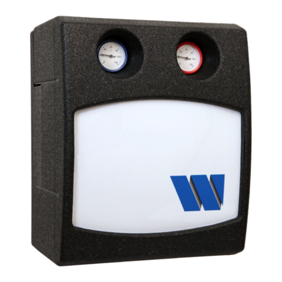
Summary of Contents for Watts FlowBox HKF25 Series
- Page 1 Series HKF25 Pump mixing valve group with thermostatic fix point control for heating systems Installation and Operating Manual WattsWater.eu...
-
Page 2: Table Of Contents
ENGLISH Contents 1 General information 1 General information ........2 1.1 Important information 1.1 Important information .............2 The operator is responsible for ensuring adherence to the local laws and regulations 1.2 Product conformity ............2 (e.g. accident prevention regulations, etc.). 1.3 Product features .............2 Incorrect operation or operating the pump 2 Safety ............ -
Page 3: Safety
ENGLISH 2 Safety The pump group is not intended to be operated by people (including children) with physical, sensory or mental disabilities, nor by people with insufficient experience or 2.1 Presentation of the safety instructions previous knowledge. DANGER indicates an imminent danger 2.4 Foreseeable misuse that may cause serious physical injury or The following is considered to be foreseeable misuse:... -
Page 4: Technical Data
ENGLISH 3 Technical data Hydraulic performance data 6 bar Max. operating pressure Ambient temperature -2 °C to +40 °C ( observe pump specification! Operating temperature +2 °C to +90 °C ( observe pump specification! 10 mbar Opening pressure of gravity brake Kvs mixing valve 0 - 120 °C Temperature display area... -
Page 5: Pressure Loss Curve
ENGLISH 4 Pressure loss curve 1.000 1.000 10.000 Flow rate [l/h] 5 Overall dimensions Rp1" Rp1" 240,5 G11/2" G11/2" HKF25-IM-DE-W-UK-11-2020-Rev.0 | Part no. 10027337... -
Page 6: Construction
ENGLISH 6 Construction 7 Installation and commissioning Electricity! Risk of death from electric shock. • Work on parts carrying live voltage must only be carried out by trained electricians. • Disconnect the power supply of the system and secure it against being switched back on before carrying out any installation, mainte- nance, cleaning or repair work. -
Page 7: Installation Diagram
ENGLISH 7.1 Installation diagram 7.3 Initial Commissioning Requirement • The pump group is completely assembled. Connection of the power supply 1. Connect the power supply (see separate pump documentation). 9 The pump group switches on automatically after being connected to the power supply. 2. -
Page 8: Exchanging The Supply And Return Line
ENGLISH 7.5 Exchanging the supply and return line 4. Loosen the nut on the return ball valve and turn the ball valve through 180 degrees. Initial situation: the supply is on the right side. 5. Rotate the pump group by 180 degrees and tighten all 9 Disconnect the power supply and secure it against connections and fittings. -
Page 9: Maintenance
ENGLISH 8 Maintenance 8.1 Annual maintenance intervals 1. General visual inspections Electricity! • Check the station for leaks and retighten sealing connec- tions or replace seals, as required. Only perform maintenance work on the pump group if the voltage supply has been 2. -
Page 10: Disassembling The Circulation Pump
ENGLISH 8.3 Disassembling the circulation pump 1. Disconnect the power supply and secure it against being switched on again. 2. Remove the front panel of the pump group. 3. Close all stop valves. 4. Disassemble thermometer handles and intermediate insulation. Risk of heavy scalding from hot water! •... -
Page 11: Disassembling Of The Thermostatic Mixing Valve
ENGLISH 8.5 Disassembling of the thermostatic mixing valve 1. Disconnect the power supply and secure it against being switched on again. 2. Remove the front panel of the pump group. 3. Close all stop valves by turning the thermometer handle. 4. -
Page 12: Disposal
Warranty: All sales and contracts for sale are expressly conditioned on the buyer’s assent to Watts terms and conditions found on its website at www.wattswater.eu/gtc/ Watts hereby objects to any term, different from or additional to Watts terms, contained in any buyer communication in any form, unless agreed to in a writing signed by an officer of Watts..


Need help?
Do you have a question about the FlowBox HKF25 Series and is the answer not in the manual?
Questions and answers