Advertisement
Series WDS-SI and LFWDS-SI
FloodSafe
Water Detector Shutoff
®
Sizes:
⁄
" and 1" (20 and 25mm)
3
4
Please read all instructions, identify all components and read all warnings prior to beginning the installation of this product.
This product is intended to prevent catastrophic water damage in the event of a water heater leak.
Please Note: During an emergency operating condition, the temperature and pressure relief valve installed on your water heater can
discharge an excessive amount of water. It is designed to protect your home or business from the potential danger of explosion. Upon
detection of this discharged water, the FloodSafe
(gas, oil or electricity) to the water heater, preventing a very dangerous situation.
The FloodSafe
Water Detector Shutoff also contains an audible & visual alarm and contacts for monitored alarm systems. It is a reset-
®
table device and can be tested at any time to ensure proper operation.
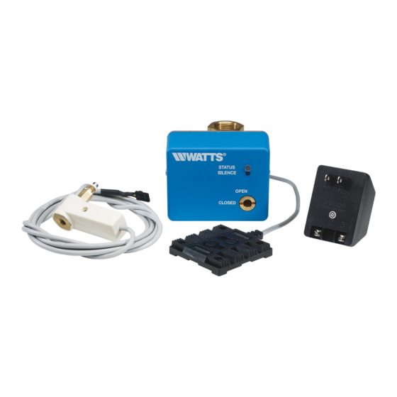
Parts Included
Control Unit
Water Detector Pad
Important Note: Thermostat wiring is required and must be supplied by the installer.
Planning Your Installation:
The Water Detector Shutoff should be installed within 6 to 12 inches of the water heater on the cold water inlet supply pipe.
The Control Unit, which houses the circuitry for the operation of the valve, contains interlocking connectors for the Water Detector Pad,
the Power Supply and remote alarm and the Power Cutout Module. The cables provided should not be cut or extended; therefore,
remote installation is not recommended.
The Water Detector Pad supplied with the Water Detector Shutoff should be located as close to the water heater as possible. It is not
necessary to remove the cover of the Control Unit to install the interconnecting cables.
Flooring Surface:
Dirt flooring – A metal or plastic drain pan must be installed under the water heater. Position the Water Detector Pad inside the
drain pan.
Cement floor – Install the Water Dam provided with the Water Detector Shutoff installation kit around the outside diameter of the
water heater. Position the Water Detector Pad inside the Water Dam.
Attic installation – A metal or plastic drain pan must be installed under the water heater. Position the Water Detector Pad inside
the drain pan.
Please be certain to follow all local codes when installing this device.
Water Detector Shutoff shuts off both the supply of water and the source of power
®
Power Cutout Module
Power Cutout Cable & Pocket Screwdriver
Power Supply
Water Dam
IS-WDS-SI
Advertisement
Table of Contents

Related Manuals for Watts FloodSafe WDS-SI Series


Summary of Contents for Watts FloodSafe WDS-SI Series
- Page 1 Series WDS-SI and LFWDS-SI IS-WDS-SI FloodSafe Water Detector Shutoff ® Sizes: ⁄ " and 1" (20 and 25mm) Please read all instructions, identify all components and read all warnings prior to beginning the installation of this product. This product is intended to prevent catastrophic water damage in the event of a water heater leak. Please Note: During an emergency operating condition, the temperature and pressure relief valve installed on your water heater can discharge an excessive amount of water.
- Page 2 Installation Instructions: a. Turn off all electrical power to the water heater. b. Turn off the water supply to the water heater. c. Drain water from the water heater so that the cold water supply piping is free of water. d.
- Page 3 OIL BURNER Remove Jumper to T T Terminals PRIMARY RELAY POWER CUTOUT MODULE POWER CUTOUT Oil Burner MODULE To Control Unit Primary Relay CONTROL UNIT To T T terminals on Oil Burner Relay Figure 7 Figure 8 Figure 9 3. Using two conductor thermostat cable (supplied by the installer) install the spade terminals to one side of the cable and fasten termi- nals to the other side of the cable.
- Page 4 Installation Continued 5. Remove the green circuit board terminal strip from the Control Unit by pulling straight out on the terminal strip. Figure 16 6. Install wiring (The wire is installer supplied. Thermostat wire is acceptable.) between the green circuit board connector and the Power Supply, observing polarity, as shown on both the Power Supply and the control panel.
- Page 5 Test the System Prior to Leaving the Installation: 1. Place enough water in the drain pan or Water Dam to actuate the Water Detector Shutoff. 2. Upon actuation, the following should take place: a. Power to the water heater should shut off immediately. b.
Need help?
Do you have a question about the FloodSafe WDS-SI Series and is the answer not in the manual?
Questions and answers