Watts 909 Series Installation, Maintenance & Repair
Relief valve
Hide thumbs
Also See for 909 Series:
- Installation instructions manual (24 pages) ,
- Instruction, installation, maintenance and repair manual (16 pages) ,
- Installation, maintenance & repair (9 pages)
Advertisement
Installation, Maintenance, & Repair
Series 909, LF909, 909RPDA, LF909RPDA
Reduced Pressure Zone Assemblies
Reduced Pressure Detector Assemblies
1
Sizes: 2
⁄
" – 10" (65-250mm)
2
WARNING
!
Read this Manual BEFORE using this equipment.
Failure to read and follow all safety and use information can
result in death, serious personal injury, property damage, or
damage to the equipment.
Keep this Manual for future reference.
WARNING
!
You are required to consult the local building and plumbing
codes prior to installation. If the information in this manual
is not consistent with local building or plumbing codes,
the local codes should be followed. Inquire with governing
authorities for additional local requirements.
WARNING
!
Need for Periodic Inspection/Maintenance: This product
must be tested periodically in compliance with local codes, but
at least once per year or more as service conditions warrant. If
installed on a fire suppression system, all mechanical checks,
such as alarms and backflow preventers, should be flow tested
and inspected in accordance with NFPA 13 and/or NFPA 25.
All products must be retested once maintenance has been
performed. Corrosive water conditions and/or unauthorized
adjustments or repair could render the product ineffective for the
service intended. Regular checking and cleaning of the product's
internal components helps assure maximum life and proper
product function.
WARNING
!
The installation and maintenance of backflow assemblies
should be performed by a qualified, licensed technician.
Failure to do so may result in a malfunctioning assembly.
NOTICE
For Australia and New Zealand, line strainers should be installed
between the upstream shutoff valve and the inlet of the backflow pre-
venter.
Testing
For field testing procedure, refer to Watts installation sheets
IS-TK-DP/DL, IS-TK-9A, IS-TK-99E and IS-TK-99D found on
www.watts.com.
For other repair kits and service parts, refer to our Backflow
Prevention Products Repair Kits & Service Parts price list
PL-RP-BPD found on www.watts.com.
For technical assistance, contact your local Watts representative.
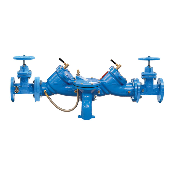
Watts 909 OSY shown
Designed for inline servicing
Basic Installation Guidelines
NOTICE
The flange gasket bolts for the gate valves should be re tight ened
during in stal la tion as the bolts may have loos ened due to stor age
and ship ping.
High Capacity Relief Series:
Location and Installation Considerations
1. Backflow preventers must be installed in high-visibility locations
in order to allow for immediate notice of telltale discharge or
other malfunction. This location should also facilitate testing and
ser vic ing, and protect against freezing and vandalism.
2. Installing a backflow preventer in a pit or vault is not rec om-
mend ed. However, if this becomes necessary, Watts highly rec-
om mends that a licensed journeyman tradesperson, who is rec-
ognized by the authority having jurisdiction, be consulted to
ensure that all local codes and required safety provisions are
met. An air gap below the relief port must be maintained so as
to avoid flooding and submersion of the assembly, which may
lead to a cross connection. *Please refer to Figure No. 1 for fur-
ther information.
3. Pipe lines should be thoroughly flushed to remove foreign mate-
rial before installing the unit. A strainer should be installed ahead
of backflow preventer to prevent disc from unnecessary fouling.
Install valve in the line with arrow on valve body pointing in the
direction of flow.
CAUTION
!
Do not install a strainer ahead of the backflow preventer on seldom-
used, emergency water lines (i.e. fire sprinkler lines). The strainer
mesh could potentially become clogged with debris present in the
water and cause water blockage during an emer gen cy.
4. Normal discharge and nuisance spitting are accommodated by
the use of a Watts air gap fitting and a fabricated indirect waste
line. Floor drains of the same size MUST be provided in case of
excessive discharge. *Please refer to Figure No. 1 and Figure
No. 2 for further in for ma tion.
5. When a 909/LF909 Series backflow preventer is installed for
dead-end service applications (i.e. boiler feed lines, cooling
tower makeup or other equip ment with periodic flow require-
ments), discharge from the relief vent may occur due to water
supply pressure fluctuation during static no-flow con di tions. A
check valve may be required ahead of the backflow preventer.
*Please see "Troubleshooting", Page 7, prior to installation.
RP/IS-909/909RPDA
Advertisement
Table of Contents

Related Manuals for Watts 909 Series


Summary of Contents for Watts 909 Series
- Page 1 4. Normal discharge and nuisance spitting are accommodated by venter. the use of a Watts air gap fitting and a fabricated indirect waste line. Floor drains of the same size MUST be provided in case of Testing excessive discharge.
- Page 2 Basic Installation Guidelines Series 909/LF909 Watts No. 909/LF909 Sizes: 2 ⁄ " – 10" (65-250mm) " – 10" (65-250mm) 6. The relief valve module on 2 ⁄ " – 10" (65-250mm) 909/LF909 Second Inlet Series assemblies may be turned to discharge to the opposite...
- Page 3 This is necessary to avoid water hammer or shock damage. G. The installation of a Watts air gap with the drain line terminating above a floor drain will handle any normal discharge or nuisance spitting through the relief valve. However, floor drain size may...
- Page 4 A, B and C. Remove all test equipment and open shutoff #2. Test Cock No. 1 Test Cock No. 2 For repair kits and parts, refer to Backflow Prevention Products Repair Kits & Service Parts price list PL-RP-BPD on www.watts.com...
- Page 5 Servicing First and Second Checks Sizes: 2 ⁄ " – 10" (65-250mm) CAUTION No special tools First and second checks required to service are not interchangeable Series 909 1. Remove the hatch cover bolts. The 909 is designed so that First Second when the bolts are backed off...
- Page 6 Servicing the Relief Valve Sizes: 2 " – 10" (65-250mm) CAUTION Adapter O-ring 1. Remove the relief valve cover bolts. The 909/LF909 is designed so that when the bolts are backed off ⁄ " all the relief valve spring load is retained by the bottom plug spring module. Be sure to verify this before removing all the bolts.
- Page 7 Use ond check. Watts No. 15 to eliminate water hammer. Replace defective second check assembly. In case of freezing; thaw, dis as sem ble and inspect internal components.
- Page 8 For more information: www.watts.com/prop65 Limited Warranty: Watts Regulator Co. (the “Company”) warrants each product to be free from defects in material and workmanship under normal usage for a period of one year from the date of original shipment. In the event of such defects within the warranty period, the Company will, at its option, replace or recondition the product without charge.
Need help?
Do you have a question about the 909 Series and is the answer not in the manual?
Questions and answers