
Related Manuals for ProfiTap C1R-1G


Summary of Contents for ProfiTap C1R-1G
- Page 1 1-LINK GIGABIT ETHERNET COPPER TAPS C1R-1G — C1P-1G — C1R-1G-48V — C1R-1G-BAT PRODUCT MANUAL www.profitap.com...
-
Page 2: Table Of Contents
Link / Activity 1.3. Speed LEDs 1.4. Link Failure Propagation 1.5. Power 1.6. Power Failure 1.6.1 Fast Failover 1.6.2 Battery Failover 1.7. Battery (C1R-1G-BAT) 1.7.1 Charging 1.7.2 Discharging 1.7.3 Maintenance 1.7.4 Battery Error 1.7.5 1.7.6 Battery Replacement 1.7.7 Switch the TAP off 2. - Page 3 This package includes: • 1 x Main TAP Unit (C1R-1G/C1P-1G/C1R-1G-48V/C1R-1G-BAT) • 1 x 90-240 VAC to 12 VDC/0.5 A PSU (C1R-1G/C1P-1G/C1R-1G-BAT only) • 2 x -48 VDC Terminal block connectors (C1R-1G-48V only) • 1 x Carrying pouch (C1P-1G only) If you have any questions, you can contact us through our website: www.profitap.com...
-
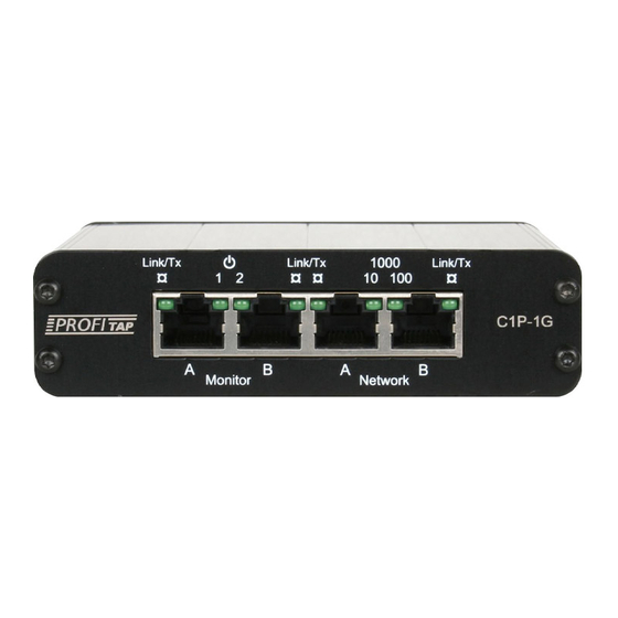
Page 4: Functional Description
100 Mbps. If both LEDs are on, the link is operating at 1 Gbps. 1.4 Link Failure Propagation Profitap Gigabit Copper TAPs transmit link failure errors between ports, allowing the network to activate a redundant path, while the TAP stays available for autonegotiation. LFP... -
Page 5: Power
1.5 Power C1-1G TAPs can use redundant powering, guaranteeing continued operation in case power from one of the power inputs were to become unavailable. Two LEDs show the presence of power. To connect the -48 VDC power to the TAP, do the following: Ensure the DC terminal block connectors are plugged into the TAP. -
Page 6: Power Failure
When the TAP becomes unpowered, it activates its bypass circuits, connecting network ports A and B together. Monitor ports are disabled when the TAP is unpowered. 1.6.1 Fast Failover (C1P-1G, C1R-1G, C1R-1G-48V) When a power transition event occurs, the network devices renegotiate the link. This operation can take up to 5 seconds depending on network configuration and can cause a network topology reconfiguration. -
Page 7: Charging
1.7.1 Charging Battery charging is indicated by a steady orange state on the BATT LED. This LED state also indicates a maintenance operation (1.7.3). The BATT LED is steady green when the battery is fully charged. The battery takes about 2 hours to charge. Overcharging protections: •... -
Page 8: Battery Error
1.7.4 Battery Error No battery The BATT LED is off if the battery is invalid or not present. Battery life suboptimal If the battery takes less than 1 hour to discharge (measured at a full discharge cycle), the BATT LED turns red after the reboot. The TAP keeps that state until the battery is replaced. In this error state, the TAP and battery still operate normally. - Page 9 Move drawer to the right Pull drawer out of the TAP Pull connector out of the TAP...
- Page 10 Disconnect the battery Install the new battery by following these steps in the reverse order...
-
Page 11: Switch The Tap Off
1.7.7 Switch the TAP off In cases in which the TAP needs to be powered off completely (e.g. for transportation), the procedure is as follows: Power the TAP on Take the battery out and disconnect it (see chapter 1.7.6 Battery replacement) Disconnect the power supply Connect the battery Put the battery back in the TAP... -
Page 12: Installation
2. INSTALLATION Power both network devices. Do NOT power the TAP. Connect the network devices to the TAP using category 5e UTP cables. • If one of the network devices is of DTE type, and the other one of DCE type, use straight cables. -
Page 13: Technical Specifications
3. TECHNICAL SPECIFICATIONS C1R-1G Connectors 4 x RJ45 8-pin gold plated LEDs 4 x Link/Activity, 2 x Network speed, 2 x Power Power Input 2 x 12 VDC (1 required for operation, 2 for redundancy) Power Consumption Dimensions (WxDxH) 113 x 128 x 30 mm — 4.4 x 5 x 1.2 in Front Panel Dimensions (WxH) 143 x 35 mm —... - Page 14 C1R-1G-48V Connectors 4 x RJ45 8-pin gold plated LEDs 4 x Link/Activity, 2 x Network speed, 2 x Power Power Input 2 x -48 VDC (1 required for operation, 2 for redundancy) Dimensions (WxDxH) 113 x 128 x 30 mm — 4.4 x 5 x 1.2 in Front Panel Dimensions (WxH) 143 x 35 mm —...
- Page 15 Legal DISCLAIMER The manufacturer makes no representations or warranties with respect to the contents hereof and specifically disclaims any implied warranties of merchantability or fitness for any particular purpose. The manufacturer reserves the right to revise this publication and to make changes in the content thereof without obligation of the manufacturer to notify any person of such revision or changes.
- Page 16 PROFITAP HQ B. V . — High Tech Campus 9 5656 AE Eindhoven — The Netherlands sales@profitap.com www.profitap.com © 2019 Profitap — v1.7-07...
Need help?
Do you have a question about the C1R-1G and is the answer not in the manual?
Questions and answers