
Related Manuals for Phenix PM1A


Summary of Contents for Phenix PM1A
- Page 1 User’s Guide PM1A Insulation Tester PHENIX TECHNOLOGIES, INC. 75 Speicher Dr. Accident, MD 21520 Copyright © Phenix Technologies, Inc. GU-1501 4/18/2017 PM1A...
- Page 2 PM1A 1 kV Digital Insulation Tester Safety Warnings Read and understand the User's guide and Safety warnings before using this equipment. ● Follow Safety procedures and rules for working near high voltage energized systems during ● the use of this equipment. The generated voltages may be dangerous.
-
Page 3: Table Of Contents
Connectors and Controls Key Functions LEDs Power Supply Low Battery Indication Charging the Battery Connecting the Equipment Setting the Equipment Timer Limit Measuring Insulation Resistance Polarization Index Low Resistance / Continuity Auto Power Off Cleaning Technical Specifications Customer Comments / Suggestions PM1A... -
Page 4: Description
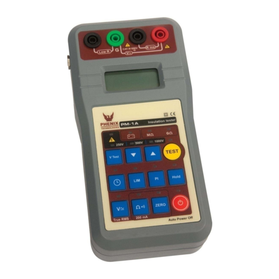
Description The PM1A is easy-to-use equipment that provides reliable, safe, and accurate measurements of insulation resistances up to 200 GΩ, with 3 test voltages: 250 V - 500 V - 1kV. Furthermore, it offers useful additional features: 200 mA continuity range, low resistance measurement, AC/DC voltage measurement up to 600 V, selectable timer, hold memory, and selectable resistance limits for pass-fail testing, with sound (beep) indication. -
Page 5: Connectors And Controls
Connectors and Controls 1. Power Supply Input 2. Terminals 3. 3 ½ digit display 4. Keyboard PM1A... -
Page 6: Key Functions
3. Press to program the test duration. 4. Press to program the limit of the Pass-Fail test. 5. Press to activate the voltmeter. 6. Press to activate low resistance / continuity. 7. Press to increase the value being programmed. PM1A... - Page 7 8. Press TEST to start / stop the test. 9. Press HOLD to freeze the displayed value. 10. Press to display Polarization Index value 11. Press to turn ON / OFF. 12. Press ZERO to compensate the test lead resistance in low resistance measurements. PM1A...
-
Page 8: Leds
Power Supply The PM1A uses a rechargeable Ni-MH battery for power (4 x 1.2 V) WARNING: Use ONLY rechargeable batteries, Ni-MH AA size, 1.2 V each, with a capacity of 1.3 Ah up to 2.5 Ah. It is dangerous to use any other type of batteries... -
Page 9: Low Battery Indication
“LO BAT” appears automatically in the display. Charging the Battery To recharge the battery: ● Check if the PM1A is turned OFF. ● Connect the equipment to the mains using the external power supply. The battery LED will continue lighting with a red light until ●... -
Page 10: Connecting The Equipment
Connecting the Equipment Connect the PM1A as follows: To measure insulation resistance: To measure insulation resistance using the Guard Terminal: To measure low resistance: To use AC/DC Voltmeter: PM1A... - Page 11 Connecting the Equipment (Cont’d Connect the test leads to the circuit and turn ON () the equipment:: NOTE; When measuring very high resistances, the operator can obtain more accurate readings by using the Guard terminal. PM1A...
-
Page 12: Setting The Equipment
LEDs. NOTE: After 5 seconds without pressing any key, the equipment enters safety mode. In this mode, the operator cannot change the selected test voltage unless the key is pressed again. This function prevents accidental changes during the measurement. PM1A... -
Page 13: Timer
“- - -” select The possible values are 5 - 10 - 15 - 30 seconds 1 - 2 - 3 - 5 - 10 - 15 minutes To cancel the Timer, repeat the above procedure and select “- - -” PM1A... -
Page 14: Limit
1 - 2 - 5 - 10 - 20 - 50- 100 GΩ The equipment will indicate with a BEEP (intermittent sound) when the insulation resistance is lower than the programmed limit. To cancel the Limit, repeat the above procedure and sele ct “- - -” PM1A... -
Page 15: Measuring Insulation Resistance
LED. The PM1A has a built-in chronometer. To see the elapsed time since test voltage is applied, press the Pressing the key during a test to show the voltage effectively applied to the element being tested. -
Page 16: Polarization Index
If the key is pressed before the 10-minute period has elapsed, the key will show PM1A... -
Page 17: Low Resistance / Continuity
Connect the test leads to the circuit to be measured. The display will show the resistance value. If the unit detects a short-circuit or the reading is R < 5 Ω ± 0,5 Ω, the equipment will indicate with a BEEP (intermittent sound Note: This function does not compensate values higher than 5 Ω. PM1A... -
Page 18: Auto Power Off
Auto-Power-off The PM1A automatically turns off after 5 minutes of non-use. In measurements with programmed time, the countdown of 5 minutes starts after the test conclusion. To turn the megohmmeter back on, press the key . Cleaning Clean this instrument by using a soft (mild) cleaning liquid, after verifying that... -
Page 19: Technical Specifications
IEC 61557- 2. During the measurement a test resistance is used with the value of UN x (1000 Ω / V). Battery charger Built-in, with external power supply of 9 V -0.5 A Operation temperature 5°C to 50° PM1A... - Page 20 Dimensions : 102 x 195 x 46 mm (4 x 3.7 x 1.9 in) Included accessories: 2 measuring test leads 1 Guard test lead 1 power supply 1 carrying bag 1 operator’s manual Subject to technical change without notice PM1A...
-
Page 21: Customer Comments/Suggestions
CUSTOMER COMMENTS/SUGGESTIONS Phenix Technologies made significant efforts to ensure that the materials in this Operator’s Manual are correct. If there are concerns or comments as you have used this information, Phenix Technologies appreciates any feedback. Unit Serial Number: Sect Page(s)
Need help?
Do you have a question about the PM1A and is the answer not in the manual?
Questions and answers