
Related Manuals for Phenix 4100-10


Summary of Contents for Phenix 4100-10
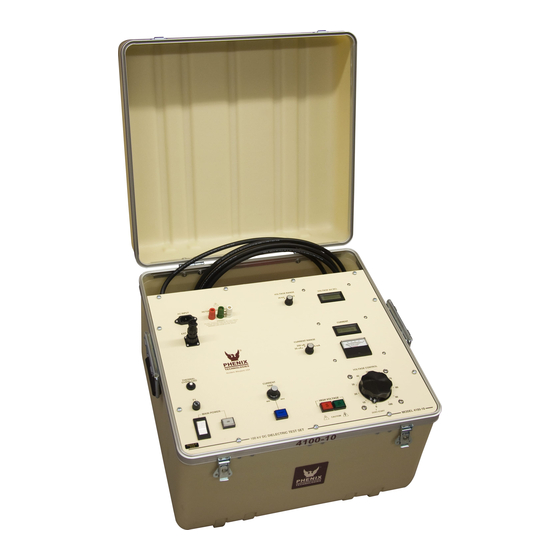
- Page 1 USER’S MANUAL DC DIELECTRIC TEST SET - 400P MODEL 4100-10 VERSION 5.2 Phenix Technologies Inc. 75 Speicher Drive Accident, MD 21520 Copyright © Phenix Technologies, Inc Rev 5/28/2015 nab DCD 4100-10...
- Page 2 INTRODUCTION The DC Hipot line offered by Phenix Technologies is ruggedly built and suitable for field or lab use. It is designed to test electrical switchgear, cables, motors, generators, and protective equipment. DC testing is popular because the equipment is more compact and lighter in weight than comparable AC equipment.
-
Page 3: Table Of Contents
DANGER / GENERAL SAFETY PRECAUTIONS TECHNICAL SPECIFICATIONS CONTROLS AND INDICATORS ELECTRICAL SET-UP OPERATING INSTRUCTIONS RETURN-GROUND-GUARD FRONT PANEL CONNECTIONS CALIBRATION TROUBLESHOOTING STORAGE OF EQUIPMENT CIRCUIT DIAGRAM SYMBOLS RECOMMENDED SPARE PARTS / PARTS LIST PARTS ORDERING INFORMATION RETURNED MATERIAL ELECTRICAL DIAGRAMS DCD 4100-10... - Page 4 DO NOT operate damaged equipment. Remove power, and do not use the equipment until safe operation can be verified by service-trained personnel. Phenix Technologies, Inc. assumes no liability for unsafe or improper use of test equipment.
-
Page 5: Technical Specifications
0-100% of selected range indication. Size and Weight 22.5" W x 21" D x 16.5" H; 98* lbs. (572 mm W x 533 mm D x 419 mm H; 44.5* kg) *For 220 V units: add 10 lbs. (4.5 kg) DCD 4100-10... -
Page 6: Controls And Indicators
SECTION 2: CONTROLS AND INDICATORS CONTROL PANEL (Refer to Figure 2-1). 1. AC POWER INPUT. Plug into a suitable grounded receptacle. See specifications tag on unit for voltage and current requirements. 2. EXTERNAL INTERLOCK. If desired, remove jumper from connector and replace with contact(s) that must be maintained closed during testing. - Page 7 This mode must be used if low potential side of test object is grounded or has a ground See section on Return – Ground – Guard for more reference. information. 21. HV OUTPUT LEAD. This lead is always attached to the high potential side of the specimen under test. DCD 4100-10...
- Page 8 CONTROLS AND INDICATORS FIGURE 2-1...
-
Page 9: Electrical Set-Up
Improper contact with the test leads on this equipment can cause harmful or fatal electrical shock. Do not touch test leads while a test is in process. This equipment should only be operated by someone familiar with high voltage testing and safety procedures. DCD 4100-10... -
Page 10: Operating Instructions
SECTION 4: OPERATING INSTRUCTIONS WARNING: This equipment should only be operated by personnel familiar with high voltage testing and safety procedures. Improper operation may result in injury or death and can cause damage to the unit or test object. Ensure proper electrical set-up has been performed. Check that the Voltage Control dial is set to "0"... - Page 11 Example: 50 uA/1,000=0.05mA. The result can now be used directly in the above formula. 10kV divided by .05mA equals 200Meg-Ohms An alternate method is to use the formula; Kilovolts divided by Microamps multiplied by 1,000 equals Meg- Ohms. KV/uA x 1,000=Meg-Ohms Example: 10kV divided by 50uA times 1,000 equals 200Meg-Ohms DCD 4100-10...
- Page 12 SECTION 5: RETURN-GROUND-GUARD CONNECTIONS The unit contains a currentmeter feature useful in measurement of different current sources. 1. Return Mode (RTN) (Grounded Return Mode) This is the standard measurement configuration. The Ground jumper is installed between the Ground (GND) post and the Return (RTN) post. The low potential side of the test specimen is connected to Return.
- Page 13 RETURN-GROUND-GUARD CONNECTIONS Figure 5-1 DCD 4100-10...
-
Page 14: Calibration
SECTION 6: CALIBRATION CAUTION: Calibration should only be done by persons familiar with High Voltage testing and safety procedures. All calibrations have been done at the factory. Periodic calibration of the output voltmeter and output currentmeter should be done annually. NOTE: Refer to Electrical Diagram Section for schematics pertaining to the model number of your test set. - Page 15 Adjust potentiometer R103 until the Overload lamp illuminates and high voltage is shut off. Repeat steps "b" through "g" as necessary until both settings are calibrated. 4. Range Overcurrent. R235 sets an overcurrent for the ranges and should be set to trip at approximately 112% of 2mA range. DCD 4100-10...
-
Page 16: Troubleshooting
If the controls do not operate properly after having been used according to the instructions, the following hints may help. Check main facility input power to the test set. Check indicating lamps. (Spare lamps are available through Phenix Technologies.) Check fuse-F1. Check all external plug connections on the test set. -
Page 17: Storage Of Equipment
1. The equipment should be covered and kept in a warm, dry environment (95% maximum humidity, 5 to 50 Celsius). 2. In no case should the test unit be stored outdoors (unless previously specified in the original purchase agreement). DCD 4100-10... -
Page 18: Circuit Diagram Symbols
SECTION 9: CIRCUIT DIAGRAM SYMBOLS CIRCUIT DIAGRAM SYMBOLS SYMBOLES POUR SCHEMA DE CIRCUIT SYMBOLE ZU SCHEMA SYMBOL DESCRIPTION DESCRIPTION BEMENKUNG Amplifier Unite d'amplificateur Verstarker ARSR Surge Arrestor Parafoudre Ueberspannungsableiter Capacitor Condensateur Kondensator BSHG Bushing Tranversee Durchfuehoung Electrolytic Capacitor Condensateur electrol Eleckrolytik kondensator Fuse Fusible... - Page 19 If the unit will be operated at an isolated site for an extended period or will be subjected to unusual stresses, a larger quantity of parts should be stocked as spares. In such cases, contact Phenix Technologies for a recommendation.
-
Page 20: Parts List
10-2 4100-10 PARTS LIST ITEM DESCRIPTION PART NO. CONTROLS C1, 4 47uF 20V Capacitor 1096510 4.7Uf, 35V Capacitor 1095010 1 uF 50V Capacitor 1094051 C5, 6,10 .033 uF 630v Capacitor 1093300 CABLE-GROUND 20 FT. GROUND CABLE ASSY. 30080011 CABLE-HV 20 FT. HV CABLE ASSY. - Page 21 10-3 4100-10 PARTS LIST ITEM DESCRIPTION PART NO. FEMALE 2 PIN CHASSIS CONN. 1151152 PIN-FEMALE 20GA 1151174 SX1 PLUG MALE 2 PIN CABLE CONN. 1151162 SX1 PLUG CABLE CLAMP 1151186 SX1 PLUG CONTACT SOLDER PINS MALE 1151176 THERMAL OVERLOAD PUSHBUTTON THERMAL CIRCUIT BREAKER-7A...
- Page 22 10-4 4100-10 PARTS LIST...
-
Page 23: Parts Ordering Information
When your purchase order is received at our office, a representative of Phenix Technologies will contact you to confirm the current price of the part being ordered. If a part you order has been replaced with a new or improved part, an Applications Engineer will contact you concerning any change in part number. -
Page 24: Returned Material
Serial Number Reason for Return Cause of Defect If Phenix Technologies, Inc. deems return of the part appropriate, it will then issue an "Authorization for Return." If return is not deemed advisable, other inspection arrangements will be made. NOTE: Material received at this plant without the proper authorization shall be held as "Customer's Property"... -
Page 25: Electrical Diagrams
13-1 SECTION 13: ELECTRICAL DIAGRAMS Drawing Number Description 9400103 4100-10 Control-Digital-PCB1257 8430101 4100-10 HV DC TANK Schematic DCD 4100-10...
Need help?
Do you have a question about the 4100-10 and is the answer not in the manual?
Questions and answers