
Subscribe to Our Youtube Channel
Related Manuals for Phenix PM6


Summary of Contents for Phenix PM6
- Page 1 OPERATIONS AND APPLICATIONS MANUAL MODEL NUMBER PM6 6 KV DC HIGH POTENTIAL TESTER WITH MEGOHMMETER Version 1.0...
-
Page 3: Table Of Contents
TABLE OF CONTENTS Section Number DANGER PRODUCT INFORMATION -SAFETY AND CAUTION NOTES -DESCRIPTION -SPECIFICATIONS CONTROLS AND CONNECTIONS -FRONT PANEL CONTROLS AND METERS -INPUT/OUTPUT CONNECTIONS INSTALLATION AND OPERATION INSTRUCTIONS -INSTALLATION -OPERATION -TEST LEAD CONNECTIONS SCHEMATIC PARTS LIST PARTS ORDERING INFORMATION RETURNED MATERIAL... - Page 4 • DO NOT operate damaged equipment. Remove power, and do not use the equipment until safe operation can be verified by service-trained personnel. Phenix Technologies, Inc. assumes no liability for unsafe or improper use of test equipment.
-
Page 5: Product Information
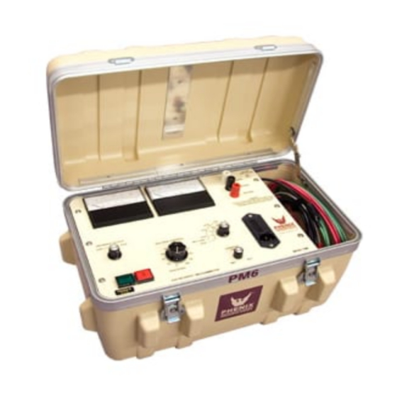
DESCRIPTION The PM6 tester is capable of producing voltages as high as 6 kV DC into a variety of insulated electrical apparatus. The unit will measure leakage current flow through (or insulation resistance levels of) the ground insulation of the test sample. Leakage current as low as .01 microamperes DC (.1 milliamperes AC) and as high as 5000 microamperes DC can be read directly from the... -
Page 6: Specifications
PRODUCT INFORMATION The unit incorporates an overcurrent trip circuit which will instantly de-energize the high voltage power supply if such a condition is encountered. The level of sensitivity at which trip-out will occur is controlled by the front panel adjustment labeled “Min-Max”. The trip setting can be as low as 10% or as high as approximately 110% of full scale reading. -
Page 7: Controls And Connections
CONTROLS AND CONNECTIONS FRONT PANEL CONTROLS AND METERS Raise Voltage: Clockwise rotation of this control increases the tester’s output voltage. The tester’s output range is 0-6,000 volts DC. This control must be returned to the “0” (full counter clockwise position) before a test can be initiated if either the “Power” or “High Voltage” switches have been previously disengaged, or if an overcurrent condition has been encountered. -
Page 8: Input/Output Connections
CONTROLS AND CONNECTIONS FRONT PANEL CONTROLS AND METERS (continued) Guard: The guard function is selected by a binding post jumper. When the jumper is connected to “Return”, leakage current or insulation resistance values associated with the “Ground” terminal will be measured. When the jumper is connected to “Guard”, leakage current or insulation resistance associated with the “Ground”... - Page 9 CONTROLS AND CONNECTIONS INPUT/OUTPUT CONNECTIONS (continued) AC Line: This cord supplies input power to the tester. Output: This test lead with clip and insulation boot supplies the testers output to the apparatus under test. Fuse: If this protective fuse opens, AC power to the tester is interrupted.
-
Page 10: Installation And Operation Instructions
INSTALLATION AND OPERATION INSTRUCTIONS INSTALLATION Install the tester as follows: 1. Turn the main “Power” switch off (out position, non-illuminated). 2. Turn the “High Voltage” power switch off (out position, non-illuminated). 3. Connect the “AC Line” cord to a 115 Volt source. 4. - Page 11 INSTALLATION AND OPERATION INSTRUCTIONS OPERATION (continued) 4. Observe and record the resultant leakage current or insulation resistance value on the “Microamperes/Megohms” meter. If no current reading is indicated, select a lower sensitivity range until an observable reading is obtained at less than full scale on the “DC Micro- amperes/Megohms”...
-
Page 12: Test Lead Connections
INSTALLATION AND OPERATION INSTRUCTIONS TEST LEAD CONNECTIONS An understanding of the function of the three current return terminals (return, ground, guard) on the tester will allow the operator to properly connect the test leads for a variety of configurations. The following points should be kept in mind when determining the proper connections for a given test requirement: 1. - Page 13 INSTALLATION AND OPERATION INSTRUCTIONS NOTES CONCERNING THE USE GUARD AND GROUND NORMAL MODE CONFIGURATION In this configuration the Return and Ground is connected together with an external jumper or a switch internal to the Test Set, depending on the design. Nothing is connected to the Guard. Both stray leakage to earth ground and leakage through the Test Specimen is indicated on the current meter.
- Page 14 INSTALLATION AND OPERATION INSTRUCTIONS GUARD MODE CONFIGURATION In this configuration the Guard and Ground is connected together with an external jumper or a switch internal to the Test Set, depending on the design. Any current associated with the Return is indicated on the current meter. Any current associated with the Guard bypasses the current meter.
-
Page 15: Schematic
SCHEMATIC Drawing Number Description 01-P124... -
Page 17: Parts List
KNOB FOR ROTARY SWITCH 1355310 POT, 10K, SENSITIVITY ADJ 1761092 KNOB, FOR ABOVE POT 1355305 ASSY. NO. 7209900500, SECTION 02 PM6 MAIN PCB ASSY PCB 31116901 BINDING POST RED (RETURN) 1351102 BINDING POST, BLK (GROUND) 1351100 BINDING POST, WHITE (GUARD) - Page 18 RES., 47M, ROX1, 6W, 1% 1746940 RES., 10K, 10W, 10% 1742190 RES., 45M, 6W, 1% 1746850 ASSY. NO. 31116901, SECTION 02 PCB1169 PM6 MAIN PCB# 1169 1111690 TRANSFORMER ST-4-24, 24V CT, 120V PRI. 1894335 RELAY, 12VDC COIL 1701035 RELAY, 120VAC COIL, 4PDT 1701300...
- Page 19 PARTS LIST (continued) ITEM DESCRIPTION PART NO. VER. RES., 500 OHM 1760500 VER. RES., 5K OHM 1761052 R2,27 VER. RES., 50 K 1761502 VER. RES., 1M OHM 1762950 RES., 120K OHM, 1/2W, 1% 1724050 R3,20 VER. RES., 100K OHM 1761950 R18,30 VER.
-
Page 20: Parts Ordering Information
When your purchase order is received at our office, a representative of Phenix Technologies will contact you to confirm the current price of the part being ordered. If a part you order has been replaced with a new or improved part, an Applications Engineer will contact you concerning any change in part number. -
Page 21: Returned Material
Serial Number Reason for Return Cause of Defect If Phenix Technologies, Inc. deems return of the part appropriate, it will then issue an "Authorization for Return". If return is not deemed advisable, other inspection arrangements will be made. NOTE: Material received at this plant without the proper authorization shall be held as "Customer's Property"...
Need help?
Do you have a question about the PM6 and is the answer not in the manual?
Questions and answers