
Related Manuals for Planet WGS-5225-8MT


Summary of Contents for Planet WGS-5225-8MT
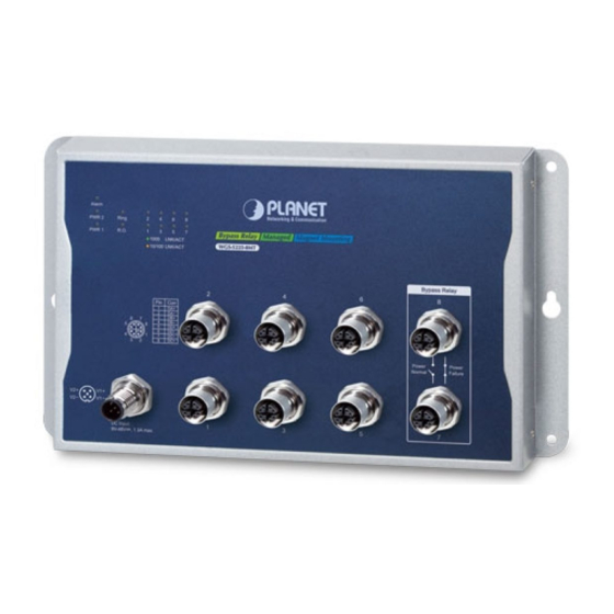
- Page 1 Industrial L2+ 8-Port 10/100/1000T M12 Wall-mount Managed Switch WGS-5225-8MT Quick Installation Guide...
-
Page 2: Table Of Contents
2.1 M12 X-coded Connector Pin Assignment ..........4 2.2 M12 (8-pin, X-coded Male) to RJ45 (8-pin) Straight-through UTP Cabling . 4 2.3 Connecting M12 Cable to the WGS-5225-8MT ........5 3. M12 DC Power Cable .................. 7 4. Requirements ..................... 8 5. -
Page 3: Package Contents
1. Package Contents Thank you for purchasing PLANET Industrial L2+ 8-Port 10/100/1000T M12 Wall- mount Managed Switch. The table below shows the model with the number of ports Model Name 10/100/1000T M12 ports, 8-pin X-coded female connector WGS-5225-8MT In the following sections, unless specified, the term “Wall-mount Managed Switch”... -
Page 4: M12 X-Coded Cable
2. M12 X-coded cable 2.1 M12 X-coded Connector Pin Assignment The WGS-5225-8MT front panel provides eight 10/100/1000BASE-T Ethernet ports in the form of M12 8-pin X-coded female connector. These ports are designed for Ethernet equipment connection through Cat5/5e UTP cables. The M12... -
Page 5: Connecting M12 Cable To The Wgs-5225-8Mt
Ethernet devices are also running in auto nego- Note tiation mode; otherwise, the Ethernet performance will be poor. 2.3 Connecting M12 Cable to the WGS-5225-8MT Follow the steps below to connect M12 cables to the WGS- 5225-8MT. Note Step 1: Turn counterclockwise to remove the waterproof caps of an M12 connector and power input. - Page 6 Step 3: Turn clockwise to tighten the cable of the M12 connector and make sure the connection is tight. Step 4: Insert the M12 power female connector into the M12 male port of the power input. Step 5: Turn clockwise to tighten the cable connecting to the M12 power connector.
-
Page 7: M12 Dc Power Cable
3. M12 DC Power Cable Pin Assignment The front panel of the Wall-mount Managed Switch provides one M12 DC power 5-pin male connector for DC power input. Please use the power cable with the M12 DC power 5-pin female connector from the Wall-mount Managed Switch package for DC power input. -
Page 8: Requirements
4. Requirements z Workstations running Windows XP/2003/Vista/7/8/2008/10, MAC OS X or later, Linux, UNIX, or other platforms are compatible with TCP/IP protocols. z Workstations are installed with Ethernet NIC (Network Interface Card) z Ethernet Port Connection Network cables -- Use network (UTP) cables with M12 (X-coded) and RJ45 connectors. -
Page 9: Hardware Installation
5. Hardware Installation 5.1 Wall Mount Installation To install the Wall-mount Managed Switch on the wall, simply follow the following steps: Step 1: It is required 4 holes with 8mm diameter on the wall; the distance between the 2 holes is 230 mm and the line through them must be horizontal. -
Page 10: Wall Hanging Installation
5.2 Wall Hanging Installation To hang the Wall-mount Managed Switch on the wall, simply follow the following steps: Step 1: Drill 2 holes (one hole on each side) with 8mm diameter on the wall; the distance between the 2 holes is 230 mm and the line through them must be horizontal. -
Page 11: Magnet Installation
5.3 Magnet Installation To install the Wall-mount Managed Switch on a magnetic surface, simply follow the following diagram: Magnet Installation Step 1: There are six holes in front, using six sets of magnets to install. Please refer to the following. Step 2: Turn the switch to the back, then screw the magnet to the middle hole. -
Page 12: Din-Rail Mounting
Please use the screw from the magnet kit to avoid breaking the device. Note 5.4 DIN-rail Mounting The DIN-rail kit is included in the package. When the wall mounting of the Wall- mount Managed Switch needs to be replaced with DIN-rail mounting, refer to the following figures to screw the DIN-rail on the Wall-mount Managed Switch. To hang up the Wall-mount Managed Switch, follow the steps below: Step 1: Screw the DIN-rail on the Wall-mount Managed Switch. - Page 13 Step 2: Lightly insert the DIN-rail into the track. 1 Push 2 Click Step 3: Check whether the DIN-rail is tightly on the track.
-
Page 14: Web Login
6. Web Login 6.1 Starting Web Management The following shows how to start up the Web Management of the Wall-mount Managed Switch. Note the Wall-mount Managed Switch is configured through an Ethernet connection. Please make sure the manager PC must be set to the same IP subnet address. - Page 15 3. After entering the password, the main screen appears as Figure 6-3 shows. Figure 6-3: Web Main Screen of Wall-mount Managed Switch The Switch Menu on the top of the Web page lets you access all the commands and statistics the Wall-mount Managed Switch provides. The Switch Menu always contains one or more buttons, such as “System”, “Switching”, “Routing”, “QoS”, “Security”, “Ring”...
-
Page 16: Saving Configuration Via The Web
6.2 Saving Configuration via the Web To save all applied changes and set the current configuration as a startup configuration, the startup-configuration file will be loaded automatically across a system reboot. 1. Click the Save icon on the top Switch Menu bar. 2. Press the “Save Configuration” button. 3. -
Page 17: Recovering Back To Default Configuration
5 seconds. After the device is rebooted, you can log in the Web interface management within the same subnet of 192.168.0.xx. Reset Figure 7-1: WGS-5225-8MT Reset Button... -
Page 18: Customer Support
8. Customer Support Thank you for purchasing PLANET products. You can browse our online FAQ resource and User’s Manual on PLANET Web site first to check if it could solve your issue. If you need more support information, please contact PLANET switch support team. PLANET online FAQs: https://www.planet.com.tw/en/support/faq Switch support team mail address: support@planet.com.tw WGS-5225-8MT User’s Manual: https://www.planet.com.tw/en/support/downloads?&method=keyword&keyword=W...