
Related Manuals for Tektronix TSG4100A-RM1


Summary of Contents for Tektronix TSG4100A-RM1
- Page 1 TSG4100A-RM1 and TSG4100A-RM2 RF Signal Generator Rackmount Kit Instructions www.tektronix.com *P075108300* 075-1083-00...
- Page 2 Copyright © Tektronix. All rights reserved. Licensed software products are owned by Tektronix or its subsidiaries or suppliers, and are protected by national copyright laws and international treaty provisions. Tektronix products are covered by U.S. and foreign patents, issued and pending. Information in this publication supersedes that in all previously published material.
-
Page 3: Table Of Contents
Table of Contents Important safety information ..................General safety summary ..................To avoid damage to equipment and personal injury ............Kit descriptions and parts lists ..................Equipment list ....................Installation instructions .................... RM1 installation ....................RM2 installation ....................TSG4100A Series RM1 and RM2 Rackmount Kit Instructions... - Page 4 Table of Contents TSG4100A Series RM1 and RM2 Rackmount Kit Instructions...
-
Page 5: Important Safety Information
Use only with specified products. Do not use rackmount on products for which it was not intended. Refer to individual product manuals for details or contact Tektronix Customer Service when in doubt. TSG4100A Series RM1 and RM2 Rackmount Kit Instructions... -
Page 6: Kit Descriptions And Parts Lists
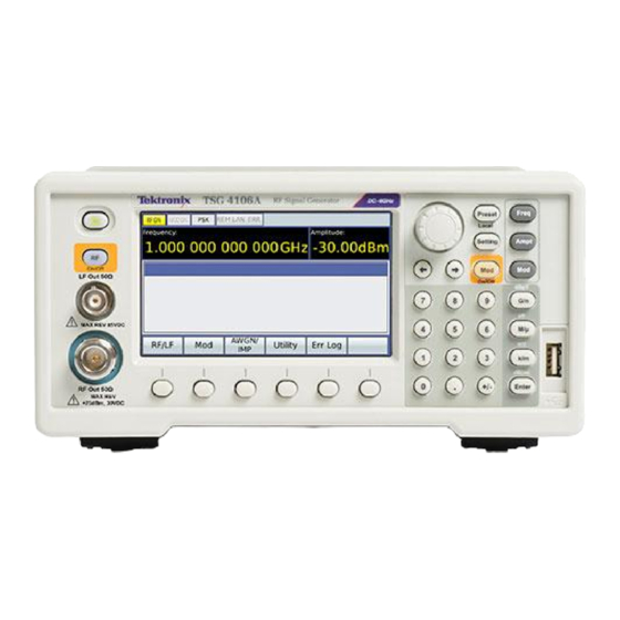
Kit descriptions and parts lists Kit descriptions and parts lists Once assembled, the following kits allow you to place one or two TSG4100A Series RF Signal Generator(s) in a standard 19-inch equipment rack. Before assembling your rackmount kit, check that you received all of the parts for the particular kit you ordered. - Page 7 Kit descriptions and parts lists TSG4100-RM1 This kit configures one Tektronix TSG4100A Series RF Signal Generator for mounting into a standard 19-inch equipment rack. This kit shipped with the items listed in the following table and shown in the following figure. (See Figure 1.) When you are ready to assemble the rackmount kit, see the RM1 installation procedure.
- Page 8 Kit descriptions and parts lists TSG4100-RM2 This kit configures two Tektronix TSG4100A Series RF Signal Generators for mounting into a standard 19-inch equipment rack. This kit shipped with the items listed in the following table and shown in the following figure. (See Figure 2.) When you are ready to assemble the rackmount kit, see the RM2 installation procedure.
-
Page 9: Equipment List
These instructions are for personnel who are familiar with servicing the product. If you need further details for disassembling or reassembling the product, refer to the appropriate product manual. Contact your nearest Tektronix Service Center or contact Tektronix Factory Service for installation assistance. - Page 10 Installation instructions Figure 3: RM1 assembly RM1 assembly procedure 1. Remove the flexible boot that surrounds and protect the front end of the instrument. 2. Remove the two T25 screws from each side of the instrument (a total of 4 screws).
-
Page 11: Rm2 Installation
Installation instructions RM2 installation Use the following procedure and refer to the illustrations to assemble the RM2 (two instruments) rackmount hardware and install the instruments into the rack. (See Figure 4.) (See Figure 5.) CAUTION. You must remove the feet from the bottom of each instrument if you intend to install them immediately above other instruments in the rack (with no clearance). - Page 12 Installation instructions Figure 5: RM2 assembly part 2 and part 3 TSG4100A Series RM1 and RM2 Rackmount Kit Instructions...
- Page 13 Installation instructions RM2 assembly procedure 1. Remove the flexible boots that surround and protect the front ends of the instruments. 2. Part 1: Attach the interior brackets to the two instruments as follows. (See Figure 4.) a. Remove the two T25 screws from each side of each instrument (a total of 8 screws).
Need help?
Do you have a question about the TSG4100A-RM1 and is the answer not in the manual?
Questions and answers