
Related Manuals for Tektronix TM 506


Summary of Contents for Tektronix TM 506
- Page 1 ektronix COMMI ED O EXCELLENCE INSTRUCTION MANUAL ektronix, Inc. P.O. Box 500 Beaverton, Oregon 97077 Serial Number _______________________ 070-1786-02 First Printing NOV 1974...
- Page 2 GARAN IE Tektronix warrants that this product is free from defects in Tektronix gibt dem K ä ufer auf dieses Gerat, da s sich in einwand- freiem Zustand befindet, eine einj ä hrige Garantie bei sachge- materials and workmanship. The warranty period is one (1) year m äß...
-
Page 3: Table Of Contents
M 506/R M 506 ABLE OF CON EN S Page LIS OF ILLUS RA IONS ........LIS OF ABLES ............iii OPERA ORS SAFE Y SUMMARY ......iv SERVICE SAFE Y SUMMARY ......... v ARNING | OPERA ORS PAR HE FOLLOWING SERVICING INS RUC IONS ARE FOR USE BY QUALIFIED PERSONNEL ONLY. - Page 4 M 506/R M 506 OF ILLUS RA IONS Figure Page TM 506/RTM 506 Power Module ....vi Interface Board ..........2-2 Rackmounting Detail ........2-4 2- 3 Dimensional Diagram ........2-3 3- 1 Semiconductor Lead Configuration ... 3-5 Light-Emitting Diode (LED) Lead Orientation ............
- Page 5 M 506/R M 506 OPERA ORS SAFE Y SUMMARY The general safety information in this part of the summary power cord into a properly wired receptacle before is for both operating and servicing personnel. Specific connecting to the product input or output terminals. A warnings and cautions will be found throughout the protective ground connection by way of the grounding manual where they apply, but may not appear in this...
-
Page 6: Service Safe Y Summary
M 506/R M 506 SERVICE SAFE Y SUMMARY FOR QUALIFIED SERVICE PERSONNEL ONLY Refer also to the preceding Operators Safety Summary. Disconnect power before removing protective panels, Do Not Service Alone soldering, or replacing components. Do not perform internal service or adjustment of this product unless another person capable of rendering first aid and resuscitation is present. - Page 7 Ce rappel des consignes générales de sécurité s'adresse à la fois aux utilisateurs et au personnel de maintenance. Avertissements et précautions à respecter sont annotés au long de ce manuei à chaque fois que l'utilisation du TM 506 l'exige. Il est à noter que ceux-ci peuvent ne pas figurer dans cette rubrique de rappel.
- Page 8 M 506/ R M 506 CONSIGNES DE SECURI E UNIQUEMEN DES INEES AU PERSONNEL DE MAIN ENANCE Ces consignes s'adressent exclusivement à un personnel qualifié. Il est également indispensable de se reporter aux consignes de sécurité précédentes. Ne pas se servir de l'appareil seul Toute intervention interne ou réglage doit s'effectuer en présence d'une autre personne capable d'assurer les premiers se ...
- Page 9 M 506/R M 506 Mise à la masse de l'appareil Une fois installé dans le châssis d'alimentation, l'appareil est relié à la masse à l'aide d'un conducteur du cordon d'alimen tation. Pour éviter tout choc électrique, insérer la prise du cordon d'alimentation dans une prise de distribution correspon dante avant de connecter l'entrée ou les sorties de l'appareil.
- Page 10 M 506/R M 506 SICHERHEI SANGABEN FUR DEN ANWENDER düng von elektrischen Schlägen vor der Beschaltung der Die allgemeinen Sicherheitsinformationen in diesem Teil der Angaben dienen dem Anwender- und Serviceperso Ein- und Ausgänge ist der Netzstecker in eine korrekt ver nal.
- Page 11 M 506/R M 506 SICHERHEI SANGABEN FÜR DEN SERVICE NUR FÜR GESCHUL ES PERSONAL Beziehen Sie sich auch auf die vorangehenden Sicherheitsangaben für den Anwender. Führen Sie keine Servicetätigkeiten alleine durch schäden sind solche Stellen und Bauteile nicht zu berüh ren, während Betriebsspannung anliegt.
- Page 12 M 506/R M 506 ご使用の前に この章では操作する方およびサービス ・ エンジニアの方 電源コードの接地線を用いて接地を行うと安全です 。 に安全にお取扱いいただくための注意事項が述べられてい ます 。 接地を行わない場合 接地が行われていないと 、 導体の部品 ( 絶縁処理された 用ミ ノブおよびコントロールつまみを含む ) により電気的ショ マニュアル中の用語 ックを變けることもあります 。 注意の 項は本機器または他の接続機器に損傷を及ぼす恐 れのある場合の注意です 。 電源一 -ド 十 ” へ 製品に適合した電源コードをご使用下さい 。 警告の 項は人体に損傷を与えたり生命に危険を及ぼす恐 れのある場合の注意です 。 故障のない電源コードをご使用下さい...
- Page 13 サービス上の注意 サービス ・ エンジニアの方へ “ 操作上の注意 ” を先にお読み下さい 。 1 人でサービスを行わないで下さい 。 パネルの取りはずし 、 ハンダ付 、 部品の交換を行う前に 機器の内部点検または修理は 、 万一の場合に備えて応急 は 、 電源を必ず切って下さい 。 処置のできる人がいる所で行って下さい 。 電源 電源を入れた場合の注意 丁 型は電源コードの線間あるいは電源コードとグラ !71506 機器内部には高電圧の部分があります 。 人体への危険を ウンド間が レ!'〇^以内の範囲の電源で作動します 。 安全 防止するため 、 電源がはいっている時は 、 露出している接 のために電源コードのアース線できちんと接地して下さい...
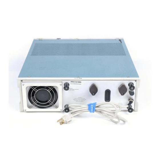
- Page 14 M 506/R M 506 M 506 Power Module rackmounted version M 506 Power Module with plug-ins 1786-01 M 506/R M 506 Power Module. @ June 1980...
-
Page 15: Specifica Ion
Description through the back panel. The TM 506 is a six-wide power module compatible Performance Conditions with all TM 500 plug-ins. It provides unregulated d c and ac supplies and non-dedicated power transistors for plug-in... - Page 16 Specification — M 506/R M 506 able 1-1 (cont) Characteristics Performance Requirements Supplemental Information 25 Vac (2 each) Range 25.0 Vrms +10%, -15% floating Maximum load Standard compartment 25 VA High-power compartment 60 VA Maximum floating voltage 350 V peak 17.5 Vac b Range With a grounded center tap 20.5 Vrms...
-
Page 17: Physical Characteristics
Specification — M 506/R M 506 able 1-3 SOURCE POWER REQUIREMEN S Supplemental Information Performance Requirements Characteristics Selectable 100 V, 110 V, 120 V, 200 V, Voltage ranges 220 V, and 240 V nominal line ±10% 48 Hz to 60 Hz Line frequency Approximately 320 W Max power consumption... - Page 18 “ With plug-ins. Some piug-ins require additional limitations. able 1-6 MECHANICAL Characteristics Supplemental Information Net weight TM 506 29.0 lbs (13.2 kg) RTM 506 32.0 lbs (14.4 kg) Overall dimensions TM 506 6.0 in (15.2 cm) H, 17.4 in (44.2 cm) W, 20.0 in (40.8 cm) L RTM 506 5.25 in (13.3 cm) H, 19.0 in (48.3 cm) W, 18.9 in (48.0 cm) L...
-
Page 19: Section 2 Opera Ing Ins Ruc Ions
After completing the installation procedure, found at the plug-ins themselves. the end of this section, and installing the plug-ins, pull the PULL ON POWER switch on the right side of the TM 506. Some plug-ins have independent power switches, usually Operating... -
Page 20: Building A System
BNC connectors and one 50-pin match the module ’ s slot location. An entire TM 506 can be connector to the rear panel. These connectors are not pre ... -
Page 21: Procedure
1/4 located near the top of the matched set. inch is required, both above and below the TM 506, to allow space for proper circulation of cooling air. Mounting Procedure. Use the following procedure to mount both sides. - Page 22 Operating Instructions — M 506/R M 506 1786-03 op view of cabinet rack. Front and rear rails are tapped for No. 10-32 screws. Fig. 2-2. Mounting the left stationary section (with its matched intermediate section, not shown in illustrations A and B) to the rack rails.
- Page 23 10-32 screw, see Fig. 2-3. Using the hardware (not furnished) indicated in Fig. 2-3, follows: secure the TM 506 to the front rails of the rack. 1. Pull the slide-out track intermediate sections out to the fully extended position.
- Page 24 Operating Instructions — M 506/R M 506 1786-04 Fig. 2-3. Dimensional diagram. English 2-6 REV D JUN 1980...
-
Page 25: Conception D'un Systeme
Considérations de charge. Afin d'employer au mieux la ca 2. Aligner les rainures supérieures et inférieures du tiroir pacité de puissance du TM 506, il faut déterminer avec grand avec les guides du compartiment sélectionné. Insérer le tiroir soin la configuration des tiroirs, les charges externes ainsi que et le pousser à... - Page 26 I'arriere de sur le connecteur. L'utilisateur du TM 506 peut done «pro- I'interface. Ils sont montes sur les emplacements des broches grammer» un ou plusieurs compartiments afin que ceux-ci 14A et B a 28A et B.
- Page 27 13,33 cm. Si l'on veut installer d'autres appa détails d'installation. reils dans la baie, il faut ménager un espace supplémentaire de 0,63 cm, au-dessus et au-dessous du TM 506 pour la libre 1. Pour monter l'appareil directement au-dessus ou au- circulation de l'air.
- Page 28 Instructions d'utilisation — TM 506/RTM 506 (B) Vue du dessus de la baie les rails arrières et frontaux taraudés pour des vis 10-32 F1 786-03 Fig. 2-2. Montage de la partie fixe gauche (avec sa partie intermédiaire correspondante, que l'on ne voit pas Fig. A et B) sur les rails conducteurs.
- Page 29 Installation et réglage du M 506 figure 2-3. A l'aide des pièces (non fournies) indiquées figure 2-3, fixer de manière sûre le TM 506 sur les rails frontaux Pour insérer l'appareil dans la baie, procéder comme suit : de la baie.
- Page 30 Instructions d'utilisation — M 506/R M 506 Fig. 2-3. Diagramme dimensionnel. French 2-6 @ June 1980...
- Page 31 Bestückt mit 6 Einschüben nimmt die Versorgungsein Für die Inbetriebnahme der TM 506 Versorgungsein heit TM 506 bis zu 320 W an einem 220 V Netz auf. Die tat heit ist es nicht zwingend, alle Einschubfächer zu bestük- sächliche Leistungsaufnahme hängt von der Kombi ...
- Page 32 Mechanisch sind die Einschübe anderen Tektronix- zwischen Einschüben und Versorgungseinheiten. Produkten sehr ähnlich, jedoch elektrisch nicht kom patibel. Aus diesem Grund besitzt die TM 506 in den Buchsenleisten zwischen den Stiften 6 und Sperriegel, wodurch das Einsetzen eines falschen Einschubes verhindert wird.
- Page 33 Geräte eingebaut, ist ein zusätzlicher Vorrichtungen installiert wird und dem Mitteilteil, das an Abstand, ober- und unterhalb des TM 506, von 0,6 cm ein die anderen beiden Teile angebracht wird, um ein völliges zuhalten, um eine ausreichende Belüftung zu gewähr ...
- Page 34 Bedienungsanleitung — TM 506/RTM 506 (B) Gestellgehäusedraufsicht. Front- und rückseitige Schienen haben Gewindelöcher für 10-32er Schrauben. G 1786-03 Abb. 2-2. Einbau des linken stationären Teils an die Gestellschienen (mit den dazu passenden Zwischenteilen, die nicht in Bild A und B dargestellt sind).
- Page 35 Teil mit den vorhandenen Montage kleinteilen anzubringen, wie in Abb. 2-2A links oder (Siehe Abb. 2-3) Zur Sicherung des TM 506 sind Klein rechts dargestellt ist. Es ist zu beachten, daß die hinte teile wie in Abb. 2-3 dargestellt (nicht mitgeliefert) zu ver ...
- Page 36 Bedienungsanleitung — TM 506/ RTM 506 2 5/8 Inch. Dieses Loch muß in jede Front- und Rückseitenschie 3 1/4 Inch zur Sicherung ne von EIA, RE MA oder Western der Frontplattenschraube Electric Gestellen gebohrt und mit einem 10-32er Gewinde versehen werden.
- Page 37 M 506/R M 506 取扱説明 取付け ーマル ・ カットアウト装置により自動的に電源が切断し 、 取付け手順に関しては本章の最後の部分に述べられてい 丁 型を保護します 。 この装置は内部温度が安全動作温 !71506 度に復帰すれば再び電源を接続します 。 ます 。 丁 型の格納温度は一 て~ でまでですが 、 機器 !71506 のシャーシが動作温度範囲内に戻ってから電源を投入して 電源 下さい 。 丁 型はアース電位の中性点を持った電源で使用する 171506 ように設計されています 。 多相システムの 相または単相 線システムの 線で動作させることはできません 。 プラグイン...
- Page 38 M 506/R M 506 システム構成 互換性 ます 。 このスペーサとカット部分が一致していることを確 当社のプラグインは外観上 、 他のシリーズ 、 認します〇 ( 7000 5000 シリーズ ) のプラグインと類似しています 。 しかし電気的 には互換性がありません 。 他のシリーズのプラグインと組 丁 シリーズのプラグインの正面左下隅のレリーズ ・ !71500 み合わせができないよう 、 丁 型のインターフェイス ・ ラッチの色は白ですので 、 他のシリーズのプラグインと簡 171506 コネクタのピン と ? に位置決めスペーサがはいっていま 単に識別できます...
- Page 39 M 506/R M 506 ネクタの後側の および すべてのピ 14A~28A 14 6-286^ 後部パネル ンの位置に ミルの四角いピンが立てられます 。 これによ 後部補助パネルは およびマルチピン・コネクタを取 り付属の角ピン ・ コネクタ付きワイヤをラジオ ・ ペンチま 付けるパンチ穴をあけることができます 。 オプションで最 たはピンセットを使って簡単に素早く配線したり 、 変更し 初から穴のあいたものもあります 。 穴があいて"\ると後か たりすることができるのでインターフェイスが容易になり ら取付けられたコネクタや配線で 、 外部 信号をインタ ます 。 またジャンパ線のハンダ付けの繰返しによるプリン ーフェイス ・ 基板に接続するのに便利です 。 ( オプション ト基板の損傷を防ぐことができます...
- Page 40 図 左側取付部 ( 中間部に合わせてありますが 、 図中には示されていません 。 ) のラック ・ ールへの取り付け 。 は工場で機器に取付けられます 。 中間部はフレームと固定 図の取付法を利用する場合には 、 前面 2. 2 ~ 2 8 部の間に収まり 、 機器をト分にラックから引き出せるよう および後部レールの穴には 〇\尸ねじ用の雌 10~32 になっています 。 ねじを切る必要があります 。 図の右図に 2-28 おいてスライドアウト ・ トラック固定部の前面フ 取付金具ースライドアウト.トラック.アセンブリに付属 ランジの支持面を増やすためには 、 ワッシャ...
- Page 41 チック ・ ラッチと中間部ストップとが組合せセットの上部 取付けることができるように 、 どちらの向きにも取付 近くにおかれてあります 。 けることができます 。 右側の固定部を取付ける際には ) 図を手引きとして用います 。 固定部が水平 2-2 ( 8 取付手順一両側の組合せセットを取付ける際には 、 下記の に調節され 、 左右が平行になっていることを確認しま 手順に従って下さい 。 詳細は 図をご参,照下さい 。 す 。 キャビネット ・ ラック内で別の機器の直上または直下 一 に機器を取付ける際には 、 図を参照して 、 前面ラ 丁...
- Page 42 WARNING THE FOLLOWING SERVICING INSTRUCTIONS ARE FOR USE BY QUALIFIED PERSONNEL ONLY. TO AVOID PERSONAL INJURY, DO NOT PERFORM ANY SERVICING OTHER THAN THAT CONTAINED IN OPERATING INSTRUCTIONS UNLESS YOU ARE QUALIFIED TO DO SO.
-
Page 43: Arning
Exterior. Loose dust may be removed with a soft cloth or a dry brush. Water and a mild detergent may be used. Six screws on the top secure the cabinet to the TM 506 However, abrasive cleaners should not be used. -
Page 44: Troubleshooting Aids
Maintenance — M 506/R M 506 ROUBLESHOO ING AIDS Power Cord Conductor Identification Conductor Color Alternate Color Introduction Ungrounded (Line) Brown Black Grounded (Neutral) Blue White The following is provided to augment information Grounding (Earthing) Green-Yellow Green-Yellow contained elsewhere in this and other TM 500 series family manuals when... - Page 45 Maintenance — M 506/R M 506 after substitution, then the power module is probably at ransistors and IC ’ s. Turn the power switch off before fault. Moving a properly operating plug-in from compart removing or replacing any semiconductor. ment to compartment will help determine if one or more compartments have a problem.
-
Page 46: Replacing
Before you purchase or order a part from a source other these, push the mounting clips away from the circuit board than Tektronix Inc., please check the electrical parts list edges to free the board. Also, remove any knobs, etc., that for the proper value, rating, tolerance and description. - Page 47 Maintenance — M 506/R M 506 Plastic-Cased ransistors Case Metal-Cased ransistors Dual FE 's Regulator IC's See manufacturers specifications Power ransistors Integrated Circuits 1786-05 Fig. 3-1. Semiconductor device lead configurations found in the M 500 family. Observe the following precautions to avoid damage: Static-Sensitive Components 1.
- Page 48 3-1 flexibility as possible. Instead, prepared jumpers, coax RELA IVE SUSCEP IBILI Y O cables, and interconnection jack barriers are included in S A IC DISCHARGE DAMAGE the TM 506. Relative Susceptibility System Design Directions Semiconductor Classes Levels* MOS or CMOS microcircuits or 1.
- Page 49 23 and 24 on J20 and between pi ns 17 and 18 contact. Keep all interface wiring away from the TM 506 on J30. primary line wiring.
- Page 50 Replaceable Mechanical Parts list. 6. To re-install the switch assembly, reverse the above If the Tektronix instrument is to be shipped to a Tektronix Service Center for service or repair, attach a tag procedure.
- Page 51 Fig. 3-3. 220 V Selector block in service. urethane foam between carton and instrument on all To determine how the TM 506 is set and if a change is sides. Seal the carton with shipping tape or an in ...
- Page 52 Maintenance — M 506/R M 506 4. Using the above noted line voltage and Table 3-2, that the appropriate number will appear in the slot, and pressing towards the instrument. determine if a change is necessary. 8. The instrument is now ready for use. 5.
- Page 53 Section 4 — M 506/R M 506 OP IONS Your instrument may be equipped with Option 2, which allows customizing of the interface. Detailed information concerning this option may be found in the following sections: Section 2 — Operating Instructions Section 3 —...
- Page 54 If a part you have ordered has been replaced with a new or improved part, your local Tektronix, Inc. Field Office or representative will contactyou concerning any change in part number.
- Page 55 644 W. 12TH ST. ERIE, PA 16512 73803 TEXAS INSTRUMENTS, INC., METALLURGICAL MATERIALS DIV. 34 FOREST STREET ATTLEBORO, MA 02703 80009 TEKTRONIX, INC. P 0 BOX 500 BEAVERTON, OR 97077 82877 ROTRON, INC. 7-9 HASBROUCK LANE WOODSTOCK, NY 12498 91637 DALE ELECTRONICS, INC.
- Page 56 Replaceable Electrical Parts — M 506/R M 506 Tektronix Serial/Model No. kt No. Part No. Dscont Name & Description Mfr Part Number 670-3303-00 B010100 B029999 CKT BOARD ASSY : INTERFACE 80009 670-3303-00 670-3303-01 B030000 CKT BOARD ASSY : INTERFACE 80009...
- Page 57 Replaceable Electrical Parts — M 506/R M 506 Tektronix Serial/Model No. Dscont Name & Description Mfr Part Number kt No. Part No. 95238 J 20 131-1078-00 CONNECTOR,RCPT ,:28/56 CONTACT 600-1 156Y256DF30 J3 0 131-1078-00 CONNECTOR,RCPT,:28/56 CONTACT 95238 600-1 156Y256DF30 CONNECTOR,RCPT,:28/56 CONTACT...
- Page 58 Values less than one are in microfarads Other ANSI standards that are used in the preparation (AF). of diagrams by Tektronix, Inc. are: Resistors = Ohms (Q). he information and special symbols below may appear in this manual. Assembly Numbers and Grid Coordinates The schematic diagram and circuit board component location illustration have grids.
- Page 60 POWER MODULE IN ERFACE PIN ASSIGNMEN S No permanent I/O assign No permanent I/O assign ments. Refer to plug-in ments. Refer to plug-in ransfoi module manuals for specific module manuals for specific power ai assignments. assignments. selector S3 and mounted which ii power...
- Page 61 POWER MODULE IN ERFACE PIN ASSIGNMEN S > No permanent I/O assign No permanent I/O assign ments. Refer to plug-in ments. Refer to plug-in module manuals for specific module manuals for specific assignments. assignments. iiiii 25 Vac winding. 25 Vac winding.
- Page 62 M 506/R M 506 DE AILED BLOCK DIAGRAM 25 Vac +33.5 V and -33.5 V SUPPLIES +33.5 V Each supply is referenced to the grounded center-tap of a secondary winding. Diode bridge CR10 supplies rectified d c in each polarity. C21, Ground C22 and C11, C12 filter the d c before it goes to PRIMARY...
- Page 63 PAR S LOCA ION GRID M 506/R M 506 GRID GRID GRID REV A JAN 1980...
- Page 64 PAR S LOCA ION GRID REV A JAN 1980...
- Page 65 PAR S LOCA ION GRID GRID CR10 CR11 CR12 CR13 8.8X1 TM506/R.TM 506 1786-16 REVC JUNE K...
- Page 67 M 506/R M 506 REV D JAN 1980...
- Page 68 M 506/R M 506...
- Page 69 REV E JAN 1980...
- Page 70 If a part you have ordered has been replaced with a new or Parts of Detail Part improved part, your local Tektronix, Inc. Field Office or Attaching parts for Parts of Detail Part representative will contact you concerning any change in part number.
- Page 71 100 WILSHIRE BLVD., SUITE 315 SANTA MONICA, CA 90401 78189 ILLINOIS TOOL WORKS, INC. SHAKEPROOF DIVISION ST. CHARLES ROAD ELGIN, IL 60120 80009 TEKTRONIX, INC. P 0 BOX 500 BEAVERTON, OR 97077 82877 ROTRON, INC. 7-9 HASBROUCK LANE WOODSTOCK, NY 12498 83385 CENTRAL SCREW CO.
- Page 72 Replaceable Mechanical Parts — M 506/R M 506 Fig. & Tektronix Index Serial/Model No. Part No. Dscont Qty 1 2 3 4 5 Name & Description Mfr Part Number 384-1243-00 EXTENSION SHAFT:POWER SWITCH 80009 384-1243-00 (ATTACHING PARTS) 211-0105-00 B010100 B018789 SCREW,MACHINE :4-40 X 0.188"100 DEG,FLH STL...
- Page 73 Replaceable Mechanical Parts — M 506/R M 506 Fig. & Index Tektronix Serial/Model No. Mfr Part Number Qty 1 2 3 4 5 Name & Description Part No. Dscont 75915 345001 1-35 352-0362-00 FUSEHOLDER: W/MOUNTING HARDWARE (ATTACHING PARTS) WASHER,NONMETAL: 0.5 ID X 0.688 INCH OD,NPRN...
- Page 74 Replaceable Mechanical Parts — M 506/R M 506 Fig. & Index Tektron ix Serial/Model No. 1 2 3 4 5 Name & Description Mfr Part Number Part No. Dscont 1-69 386-3002-00 B010100 B010909 SUPPORT,XFMR:UPPER 80009 386-3002-00 (STANDARD ONLY) 386-3002-01 386-3002-01 B010910 B018339 SUPPORT,XFMR:UPPER 80009...
- Page 75 Replaceable Mechanical Parts — M 506/R M 506 Fig. & Index Tektronix Serial/Model No. Mfr Part Number Part No. Dscont Qty 1 2 3 4 5 Name & Description . CHASSIS INCLUDES: 348-0509-00 XB030000 . GROMMET,PLASTIC : BLACK,ROUND, 0.188 ID...
- Page 76 Replaceable Mechanical Parts — M 506/R M 506 Fig. & Index Tektronix Serial/Model No. Part No. Dscont Qty 1 2 3 4 5 Name & Description Mfr Part Number 200-0728-00 COV,HANDLE END: 80009 200-0728-00 367-0116-00 HANDLE,CARRYING: 12136 (ATTACHING PARTS) 212-0616-00 SCREW,SHOULDER: 10-32 X 0.531"...
- Page 77 Fig. & Tektronix Index Serial/Model No. Part No. Dscont Qty 1 2 3 4 5 Name & Description Mfr Part Number COVER,CONN:MOLD PLASTIC W/HARDWARE 08051 DD51216-1 131-1319-00 71468 DD-50S CONNECTOR,RCPT, :50 FEMALE CONTACT 131-1345-00 CONNECTOR , PLUG ,:5 0 CONT , MALE D...
- Page 78 MANUAL , TECH : INSTRUCTION 070-1876-02 80009 351-0101-00 B010100 B012129 SLIDE,DWR,EXT: 18.0 X 1.69 351-0101-00 80009 (RACKMOUNT ONLY) B012130 351-0195-00 SLIDE,DWR,EXT: 23.0 L X 1.69 06666 C719 (RACKMOUNT ONLY) 200-1728-00 COVER,FRONT(OPTIONAL) 80009 200-1728-00 REV D JUN 1980 TM 506/R M 506...
- Page 79 MANUAL CHANGE INFORMA ION At Tektronix, we continually strive to keep up with latest electronic developments by adding circuit and component improvements to our instruments as soon as they are developed and tested. Sometimes, due to printing and shipping requirements, we can ’ t get these changes immediately into printed manuals.
- Page 80 REPLACEMEN Calibration est Equipment Chart This chart compares TM 500 product performance to that of older Tektronix equipment. Only those characteristics where significant specification differences occur, are listed. In some cases the new instrument may not be a total functional replacement. Additional support instrumentation may be needed or a change in calibration procedure may be necessary.
Need help?
Do you have a question about the TM 506 and is the answer not in the manual?
Questions and answers