Table of Contents
Advertisement
Quick Links
Service Manual
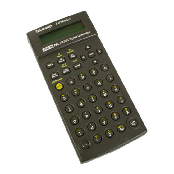
TSG 95
PAL/NTSC Signal Generator
070-8917-04
Warning
The servicing instructions are for use by qualified
personnel only. To avoid personal injury, do not
perform any servicing unless you are qualified to
do so. Refer to all safety summaries prior to
performing service.
www.tektronix.com
Advertisement
Table of Contents

Subscribe to Our Youtube Channel
Related Manuals for Tektronix TSG 95


Summary of Contents for Tektronix TSG 95
- Page 1 Service Manual TSG 95 PAL/NTSC Signal Generator 070-8917-04 Warning The servicing instructions are for use by qualified personnel only. To avoid personal injury, do not perform any servicing unless you are qualified to do so. Refer to all safety summaries prior to performing service.
- Page 2 Copyright Tektronix, Inc. All rights reserved. Tektronix products are covered by U.S. and foreign patents, issued and pending. Information in this publication supercedes that in all previously published material. Specifications and price change privileges reserved. Printed in the U.S.A. Tektronix, Inc., P.O. Box 1000, Wilsonville, OR 97070–1000...
- Page 3 Tektronix, with shipping charges prepaid. Tektronix shall pay for the return of the product to Customer if the shipment is to a location within the country in which the Tektronix service center is located.
- Page 5 Television Products Division P.O. Box 500 Beaverton, Oregon U.S.A. declare under our sole responsibility that the TSG 95 PAL/NTSC Signal Generator to which this declaration relates is in conformity with the following standards: EN50081-1, Generic Emission Standard EN50082-1, Generic Immunity Standard...
- Page 6 TSG 95 Service Manual...
-
Page 7: Table Of Contents
2–2 Connecting the TSG 95 ........ -
Page 8: List Of Figures
......1–30 Figure 1–30: NTSC 75% Color Bars, Zero Setup ....1–30 TSG 95 Service Manual... -
Page 9: List Of Tables
....... . . 1–40 Figure 3–1: TSG 95 Block Diagram ...... - Page 10 ..... . 1–13 Table 2–1: TSG 95 Video Test Signals ......
-
Page 11: General Safety Summary
(local AC) supply. Use Proper Fuse. Use only the fuse type and rating specified for this product. Do Not Operate in Wet/Damp Conditions. Do Not Operate in an Explosive Atmosphere. TSG 95 Service Manual... - Page 12 This product contains a Nickel Cadmium (NiCd) battery, which must be recycled or disposed of properly. For the location of a local battery recycler in the U.S. or Canada, please contact: RBRC (800) BATTERY Rechargeable Battery Recycling Corp. (800) 227-7379 P.O. Box 141870 www.rbrc.com Gainesville, Florida 32614 TSG 95 Service Manual...
-
Page 13: Service Safety Summary
Only qualified personnel should perform service procedures. Read this Service Safety Summary and the General Safety Summary before performing any service procedures. Use the Proper Fuse Use only the type and rating fuse specified for this product. TSG 95 Service Manual... - Page 14 Service Safety Summary viii TSG 95 Service Manual...
-
Page 15: Specifications
Electronic Measuring Apparatus”; IEC 348 Canadian Standards Association Electrical Standard for Electrical and Electronic Measuring and Testing Equipment; CAN/CSA C22.2 No. 231 Standard for Electrical and Electronic Measuring and Testing Equipment, Second Edition, July 21, 1980 TSG 95 Service Manual 1–1... -
Page 16: Performance Conditions
25 C, is being operated within environmental limits (see Table 1–11), and has had a minimum warm-up of 20 minutes. Safety Standard Compliance The following safety standards apply to the TSG 95: ANSI S82 — Safety Standard for Electrical and Electronic Test, Measuring, Controlling, and Related Equipment, 1988. -
Page 17: Specification Tables
Measured at the 50% point of active video. Breezeway Duration Digitally derived 900ns 50 ns Line Sync Duration Digitally derived 4.7µs 50 ns at half-amplitude Vertical Serration Duration Digitally derived 4.7µs 50 ns at half-amplitude TSG 95 Service Manual 1–3... - Page 18 79.8 627.3 347.1 75% Bars over Red See Figures 1–1 and 1–3. Luminance Rise Times 150 ns Field Timing Color Bars Lines 24–166 & 336–478 Lines 167–310 & 479–622 Packet Characteristics See 75% Bars, above. 1–4 TSG 95 Service Manual...
- Page 19 See Figure 1–14. White Reference Bar Amplitude 420 mV p–p Packet Amplitudes 420 mV (equal width packets) p–p Pedestal 350 mV Burst Frequencies 0.5, 1.0, 2.0, 4.0, 4.8, and 5.8 MHz Packet Rise Time 350 ns typical TSG 95 Service Manual 1–5...
- Page 20 All remaining active lines; see Figure 1–9. Amplitude 700 mV Table 1–3: PAL Vertical Interval Test Signals (VITS) Waveform Line(s) CCIR 17 CCIR 18 ITS 1 19 and 332 ITS 2 20 and 333 CCIR 330 CCIR 331 1–6 TSG 95 Service Manual...
- Page 21 Digitally derived 2.3 µs 100 ns HAD Equalizing Pulse Duration Digitally derived Burst 5.308 µs 35 ns (19 cycles of subcarrier) Delay from Sync Digitally derived 2.51 µs 0.1 µs (9 cycles of subcarrier) Duration TSG 95 Service Manual 1–7...
- Page 22 (Pedestal, mV) (degrees) p–p White 535.1 00.0 00.0 Yellow 476.8 479.3 167.1 Cyan 375.0 677.5 283.5 Green 316.1 632.6 240.7 Magenta 219.6 632.6 60.7 160.7 677.5 103.5 Blue 58.9 479.3 347.1 –I 285.7 303.0 285.7 33.0 1–8 TSG 95 Service Manual...
- Page 23 0 or 100 IRE flat field Rate 1.0 second high, 1.0 second low Field Square Wave See Figure 1–39. Field Timing Lines (White) Lines 70-213 Lines at Blanking All remaining active lines Amplitude 714.3 mV (100 IRE) TSG 95 Service Manual 1–9...
- Page 24 All Other Packets 400 ns typical (sine-squared packets) Modulated Pedestal Pedestal Amplitude 357.2 mV (50 IRE) Chrominance Amplitudes 142.9 mV (20 IRE), 285.7 mV (40 IRE), and 571.4 mV (80 IRE) Phase Rise Time 400 ns 1–10 TSG 95 Service Manual...
- Page 25 See Figure 1–48. Amplitude 549.1 mV (76.9 IRE) Safe Title Horizontal Bar Lines 45 and 238 14.925 and 56.525 µs Vertical Timing Safe Action Horizontal Bar Lines 33 and 250 12.325 and 59.125 µs Vertical Timing TSG 95 Service Manual 1–11...
- Page 26 Channel 1, 1 click Channel click outputs are offset for positive Channel 2, 2 clicks channel identification. Table 1–9: Physical Characteristics Characteristic Information Height 5.6 cm (2.2 in) Width 9.1 cm (3.6 in) Depth 19.1 cm (7.5 in) 1–12 TSG 95 Service Manual...
- Page 27 Table 1–9: Physical Characteristics (Cont.) Characteristic Information Net Weight TSG 95 0.48 kg (1.06 lb) TSG 95 with battery pack 0.68 kg (1.5 lb) Shipping Weight (with AC adapter) 1.50 kg (3.31 lb) Table 1–10: Power Supply Characteristic Performance Requirements...
-
Page 28: Pal Waveform Diagrams
PAL Waveform Diagrams NOTE. Time references in the following waveform diagrams apply to the signal half-am- plitude points or pulse peaks, unless indicated otherwise. Figure 1–1: PAL 75% Color Bars Figure 1–2: PAL 100% Color Bars 1–14 TSG 95 Service Manual... -
Page 29: Figure 1-3: Pal 75% Red And Red Field
Specifications Figure 1–3: PAL 75% Red and Red Field Figure 1–4: PAL 100% Red TSG 95 Service Manual 1–15... -
Page 30: Figure 1-5: Pal Green Field
Specifications Figure 1–5: PAL Green Field Figure 1–6: PAL Blue Field 1–16 TSG 95 Service Manual... -
Page 31: Figure 1-7: Pal 50% Flat Field
Specifications Figure 1–7: PAL 50% Flat Field Figure 1–8: PAL 100% Flat Field TSG 95 Service Manual 1–17... -
Page 32: Figure 1-9: Pal 0% Flat Field
Specifications Figure 1–9: PAL 0% Flat Field Figure 1–10: PAL Convergence (vertical lines) 1–18 TSG 95 Service Manual... -
Page 33: Figure 1-11: Pal Convergence (Horizontal Lines)
Specifications Figure 1–11: PAL Convergence (horizontal lines) Figure 1–12: PAL 5 Step (Gray Scale) TSG 95 Service Manual 1–19... -
Page 34: Figure 1-13: Pal Modulated 5 Step
Specifications Figure 1–13: PAL Modulated 5 Step Figure 1–14: PAL Multiburst 1–20 TSG 95 Service Manual... -
Page 35: Figure 1-15: Pal Reduced Sweep
Specifications Figure 1–15: PAL Reduced Sweep Figure 1–16: PAL Pluge TSG 95 Service Manual 1–21... -
Page 36: Figure 1-17: Pal Matrix Signal - Ccir 17
Specifications Figure 1–17: PAL Matrix Signal — CCIR 17 Figure 1–18: PAL Matrix Signal — CCIR Line 330 1–22 TSG 95 Service Manual... -
Page 37: Figure 1-19: Pal Matrix Signal - Ccir Line 331
Specifications Figure 1–19: PAL Matrix Signal — CCIR Line 331 Figure 1–20: PAL Matrix Signal — CCIR 18 TSG 95 Service Manual 1–23... -
Page 38: Figure 1-21: Pal Matrix Signal - (Sin X)/X
Specifications Figure 1–21: PAL Matrix Signal — (Sin x)/x Figure 1–22: PAL Matrix Signal — 15 kHz Square Wave 1–24 TSG 95 Service Manual... -
Page 39: Figure 1-23: Pal Matrix Signal - Shallow Ramp
Specifications Figure 1–23: PAL Matrix Signal — Shallow Ramp Figure 1–24: PAL Matrix Signal — UK ITS 1 TSG 95 Service Manual 1–25... -
Page 40: Figure 1-25: Pal Matrix Signal - Uk Its 2
Specifications Figure 1–25: PAL Matrix Signal — UK ITS 2 1–26 TSG 95 Service Manual... -
Page 41: Figure 1-26: Pal Safe Area
Specifications Figure 1–26: PAL Safe Area TSG 95 Service Manual 1–27... -
Page 42: Ntsc Waveform Diagrams
Specifications NTSC Waveform Diagrams Figure 1–27: SMPTE (NTSC) Color Bar Components 1–28 TSG 95 Service Manual... -
Page 43: Figure 1-28: Smpte (Ntsc) Color Bars, Zero Setup
Specifications Figure 1–28: SMPTE (NTSC) Color Bars, Zero Setup TSG 95 Service Manual 1–29... -
Page 44: Figure 1-29: Ntsc 75% Color Bars
Specifications Figure 1–29: NTSC 75% Color Bars Figure 1–30: NTSC 75% Color Bars, Zero Setup 1–30 TSG 95 Service Manual... - Page 45 Specifications Figure 1–31: NTSC Red Field Figure 1–32: NTSC Red Field, Zero Setup TSG 95 Service Manual 1–31...
- Page 46 Specifications Figure 1–33: NTSC (Sin x)/x Figure 1–34: NTSC 5 Step Staircase (Gray Scale) 1–32 TSG 95 Service Manual...
- Page 47 Specifications Figure 1–35: NTSC 0 IRE No Burst Figure 1–36: NTSC 30 IRE (Zero Setup) and 50 IRE Flat Fields TSG 95 Service Manual 1–33...
- Page 48 Specifications Figure 1–37: NTSC Black Burst Figure 1–38: NTSC Black Burst, Zero Setup (and Bounce, Low) 1–34 TSG 95 Service Manual...
- Page 49 Specifications Figure 1–39: NTSC 100 IRE, Field Square Wave (and Bounce, High) Figure 1–40: NTSC Multiburst TSG 95 Service Manual 1–35...
- Page 50 Specifications Figure 1–41: NTSC Convergence Components 1–36 TSG 95 Service Manual...
- Page 51 Specifications Figure 1–42: NTC7 (NTSC) Composite Figure 1–43: NTC7 (NTSC) Combination TSG 95 Service Manual 1–37...
- Page 52 Specifications Figure 1–44: FCC (NTSC) Composite Figure 1–45: NTSC Cable Multiburst 1–38 TSG 95 Service Manual...
- Page 53 Specifications Figure 1–46: NTSC Cable Sweep Figure 1–47: NTSC Matrix TSG 95 Service Manual 1–39...
- Page 54 Specifications Figure 1–48: NTSC Safe Area 1–40 TSG 95 Service Manual...
-
Page 55: Operating Information
Operating Information This section duplicates material contained in the TSG 95 User manual (Tektronix part number 070-8916-XX). This material is included for your convenience. Please check the User manual if you need additional information on any topic. 2–1 TSG 95 Service Manual... -
Page 56: Getting Started
(1-800-835-9433), between 8:00 am and 5:00 pm Pacific time. Supplying Power The TSG 95 is DC powered. You may power it with the standard AC adapter, the optional 9.6 V NiCad battery pack, eight standard AA batteries, or a “BP” type battery pack with the correct voltage and polarity. - Page 57 To install AA batteries or the battery pack, open the battery compartment of the TSG 95 by pressing down on the cover and sliding it in the direction of the in- scribed arrow, as shown above. When the cover tabs line up with the slots in the case, lift the cover away from the instrument.
-
Page 58: Connecting The Tsg 95
Operating Information The TSG 95 can sense low battery voltage. It will warn you when the charge is sufficient for approximately ten more minutes of operation. The instru- ment will shut itself down when the battery voltage becomes too low for reliable operation. -
Page 59: Definitions
There are two terms used in this manual that deserve a little explanation: Signal Set. The group of signals that can be selected through the TSG 95 keypad at a given time. In the pre-programmed signal sets, all of the signals are the same video standard. -
Page 60: Other Settings
Auto Power Down passed without a key press. Enable this feature when using battery power and operating in an environment in which unplanned shutdown of the TSG 95 is per- missible. 1. While still in the Utility menu, use the keys to scroll to the AUTO PWR DOWN item. -
Page 61: Using Your Tsg 95
Operating Information Using Your TSG 95 Here is a list of what you can do with your TSG 95. Instructions for each use be- gin on the indicated page. Output either PAL or NTSC video test signals (page 2–8). You can... - Page 62 Operating Information Outputting Test Signals 1. Connect the TSG 95 to your system and make the appropriate preliminary settings as described in the Getting Started section of this manual. 2. Switch the instrument on or return to normal operation by pressing either the Bars or Other Signals key.
- Page 63 2. Use the keys to select the desired level. When manufactured, the four TSG 95 tone levels are designated as –10, 0, +4, and +8 dBu and cali- brated to those amplitudes. Qualified technicians may rename and recalibrate the tone levels to any integer value within the ranges of –10 to –3 dBu and 0 to +10 dBu.
- Page 64 TSG 95 display, as shown in the next illustration. Editing ID Messages Only the current ID message may be edited in the TSG 95.. The “current” mes- sage is the ID that will appear in the output if ID=on. (The current ID will not appear in the output when ID=off, and may not appear in the output if ID=cyc, but it can still be edited and saved in either case.)
- Page 65 ID message numbers, ID# 1 through ID# 8. The first line of the message will appear on the second dis- play line; press the key to see the second line of the message. For exam- 2–11 TSG 95 Service Manual...
- Page 66 ID is toggled On with the ID On/ Off key, and the ID CYCLE item of the ID menu is set to “on.” When those two conditions are met, the TSG 95 display will indicate ID=cyc during normal op- eration.
- Page 67 ID menu. The cycle sequence information will be written to the instrument memory. Note that the TSG 95 “remembers” the ID#, not the actual message. Therefore, if you save a new message as ID# 1, the new message will appear the next time an ID cycle comes to a time interval in which ID# 1 is displayed.
- Page 68 3. When the desired storage number is displayed, press Enter to recall the pre- set. The video and audio output of the TSG 95 will return to the signal and tone that was selected when the preset was stored.
-
Page 69: Theory Of Operation
Theory of Operation This section contains a description of the TSG 95 circuitry based on the block diagram shown in Figure 3–1. Circuit Description This document describes the circuits of the TSG 95. The instrument consists of a keyboard, LCD, microprocessor, clock oscillator, character ID generator, digital timing and signal generation, video DAC and output, audio tone generation, and power supply. - Page 70 ASIC. Two of the analog-to-digital converter (ADC) inputs on the P are used. One monitors the battery or input voltage (VIN). A resistive divider (R28 and R29) 3–2 TSG 95 Service Manual...
- Page 71 YC/horizontal counter. Counting off Cb, Y, Cr, Y to form eight points of Y data in segments of multiplexed Y and C data. The lsb does the toggling between Y and C data, while the next three bits count off the eight points. 3–3 TSG 95 Service Manual...
- Page 72 C6, and C7; C7 and R71 are used to vary the amount of correction. The output of the op-amp (U11) is connected to R13, which is the 75 Ω output resistance of the TSG 95. 3–4 TSG 95 Service Manual...
- Page 73 U17 provides output amplification for the channel 2 tone in the same manner. Power Supply Power is applied to the TSG 95 either through a DC input jack on the side of the instrument, or through batteries in the battery compartment. The input voltage should be limited to 15 V to avoid a higher than suggested charge rate for the NiCad battery pack.
- Page 74 L9 also helps to filter the +5 V and –5 V sup- plies along with C53, C54, and C77. L2 and L3 are used to filter the supplies which are used in analog portions of the circuitry. 3–6 TSG 95 Service Manual...
-
Page 75: Performance Verification And Adjustment Procedures
Performance Verification and Adjustment Procedures This section consists of a detailed performance verification procedure to verify the operation of the TSG 95, and an adjustment procedure to return the instru- ment to in-spec operation. The order of these procedures has been chosen to minimize changes in equip- ment setup. - Page 76 Tektronix p/n 012-0074-00. 75 Ω, 0.025% termination with End-Line Termination Tektronix p/n 011-0102-01. BNC connector. (Add 600 Ω resistor across +/– conductors inside XLR shell) Figure 4–1: XLR Female to Mini XLR Male Adapter Cable/Pinout 4–2 TSG 95 Service Manual...
-
Page 77: Performance Verification Checklist
Performance Verification and Adjustment Procedures Performance Verification Checklist Use the following checklist if you are familiar with the operation of the TSG 95 as well as video and audio performance verification techniques. Step-by-step instructions for all of the procedures begin on page 4–4. -
Page 78: Performance Verification Procedures
< > symbols. For example: Measure hard key, and <H_Timing> soft key. Preparation The VM700A Auto Measure mode is used in this procedure. If you cannot find a specific measurement in Auto mode, check that the measurement is selected in 4–4 TSG 95 Service Manual... - Page 79 Record the currently used measurements location file so that when you have finished testing the TSG 95 you can return the VM700A to the original settings. e. Press your finger over the “XXXXX” readout; a box should now appear around the readout.
- Page 80 < Leave Directory > then go to step 7. e. Record the currently used measurements location file so that when you have finished testing the TSG 95 you can return the VM700A to the original settings. Press your finger over the “XXXXX” readout; a box should now appear around the readout.
- Page 81 Thereafter, a 20 minute warm-up time is sufficient. 1. Check Subcarrier Frequency a. Connect the TSG 95 Video output to the genlock input of the NTSC test signal generator with a 75 Ω coaxial cable as shown in Figure 4–2.
- Page 82 Complete the following steps to verify PAL performance of the TSG 95. 1. Check Blanking Level a. Connect the TSG 95 Video output to the VM700A Channel A Input and terminate the loopthrough in 75 Ω. b. Select the Matrix signal from the TSG 95 (press R).
- Page 83 CHECK — that Sync Level is 300 mV 14 mV. 3. Check Burst Amplitude a. Select the Matrix signal from the TSG 95 (press R). b. Press the following keys: Measure, <H_Timing>, and Average. c. CHECK — that the Burst Amplitude is 300 mV 14 mV.
- Page 84 Performance Verification and Adjustment Procedures 5. Check 5-Step Linearity a. Select the Matrix signal from the TSG 95 (press R). b. Press the following VM700A keys: Measure, <Luminance NonLinear- ity>, and Average. c. CHECK — that Luminance Non Linearity is 1% (99 <Lum Non-Lin-...
- Page 85 Performance Verification and Adjustment Procedures 6. Check Luminance Amplitude Accuracy a. Select the Matrix signal from the TSG 95 (press R). b. Press the following VM700A keys: Measure, <Bar LineTime>, and Average. c. Use the VM700A front-panel knob to select line 265.
- Page 86 VM700A so that the following checks can be made in Auto mode. 10. Line Tilt a. Select the Matrix signal from the TSG 95 (press R), then press the VM700A Auto key. b. Check the VM700A display to verify that Line Time Distortion is no greater than 0.5%.
- Page 87 CHECK — the VM700A display to verify that SCH Phase is 0 13. Field Tilt Distortion a. If the TSG 95 ID is on, turn it off by pressing the ID On/Off key. b. Select the Field Square Wave from the TSG 95 (Press S) then press the VM700A Auto key.
- Page 88 CHECK — that Level (b) = 0 V 50 mV. 2. Check Sync Amplitude a. Select the NTC7 Composite signal from the TSG 95 (press K). b. Press the following VM700A keys: Measure, <Bar LineTime>, and Average. c. CHECK — that Sync Amplitude is 285.7 mV 14.28 mV (40 IRE...
- Page 89 140 ns 20 ns. See Figure 4–6. 5. Check 5-Step Linearity a. Select the NTC7 Composite signal from the TSG 95 (press K). b. Press the following VM700A keys: Measure, <Luminance NonLinear- ity>, and Average. c. CHECK — that Luminance Non Linearity is 1% (99 <Lum Non-Lin-...
- Page 90 Performance Verification and Adjustment Procedures Figure 4–7: VM700A Luminance “Non Linearity” Measurement Screen 6. Check Luminance Amplitude Accuracy a. Select the NTC7 Composite signal from the TSG 95 (press K). b. Press the following VM700A keys: Measure, <Bar LineTime>, and Average.
- Page 91 Performance Verification and Adjustment Procedures Bar Level Figure 4–8: VM700A Bar Level Measurement Screen 4–17 TSG 95 Service Manual...
- Page 92 1 , and Differential Gain is 9. Check Frequency Response a. Select the Multiburst signal from the TSG 95 (press J). b. Press the following VM700A keys: Measure, <MultiBurst>, Select Line, and Average. c. Use the VM700A front-panel knob to select line 100.
- Page 93 NOTE. The VM700A Line Time Distortion measurement is equivalent to the Line Tilt characteristic called out in the Specifications section of this manual. 11. 2T Pulse K-Factor Check the VM700A display to verify that the 2T Pulse K-Factor is no greater than 0.5%. 4–19 TSG 95 Service Manual...
- Page 94 CHECK — the VM700A display to verify that SCH Phase is 0 13. Field Tilt Distortion a. If the TSG 95 ID is on, turn it off by pressing the ID On/Off key. b. Select the Field Square Wave from the TSG 95 (Press S) then press the VM700A Auto key.
- Page 95 CHECK — that both channels have a THD 2. Check Audio Output Amplitude a. Set the TSG 95 Frequency to 1 kHz and the Audio Level to 0 dBu with these steps (as necessary): Open the Tone menu by pressing Shift–Tone On/Off.
-
Page 96: Adjustment Checklist
Performance Verification and Adjustment Procedures Adjustment Checklist Use the following checklist if you are familiar with TSG 95 operation and adjust- ment. Step-by-step instructions for all of the procedures begin on page 4–24. 1. Adjust LCD Contrast Adjust R1 so that unused LCD segments are just barely turned off 2. - Page 97 0.1 dBu with the keys Change Calibration menu to 4 dBu Adjust to 4 dBu 0.1 dBu with the keys Change Calibration menu to 8 dBu Adjust to 8 dBu 0.1 dBu with the keys 4–23 TSG 95 Service Manual...
-
Page 98: Adjustment Procedures
Reinstall the tape cover on the oscillator. 3. Adjust PAL DC Gain and Blanking Level a. Connect the TSG 95 Video output to the VM700A Channel A Input and terminate the loopthrough in 75 Ω. b. Select the PAL Matrix signal from the Pathfinder (press R). - Page 99 See Figure 4–10. g. Press the Average key. h. ADJUST — R52 for Level (b–a) = 700 mV 2 mV. Press the <DC Cpl. ABS. Meas> and <Pos. (b)> keys. Position the cursor on the back porch. 4–25 TSG 95 Service Manual...
- Page 100 20 mV. m. Repeat steps d. through l. 4. Adjust NTSC Gain a. Change the TSG 95 video standard to NTSC and select the NTC7 Com- posite signal (Press K). b. Press the following VM700A keys: Measure, <Video Standard>, <Level Meter>, Menu, <Measure Position>, and Select Line.
- Page 101 NOTE. These two adjustments are interactive, but L7 mostly affects the delay and C7 the gain. 7. Adjust 2T Pulse K-Factor a. Select the Matrix signal from the TSG 95 (press R). b. Press the following VM700A keys: Measure, <K_Factor>, Menu, <Graticule>, and <Graticule Gain>.
- Page 102 PAL adjustments, and therefore should only be readjusted if they are out of specification. 10. Adjust NTSC Multiburst a. Change the TSG 95 video standard to NTSC and select the Multiburst signal (Press J). b. Press the following VM700A keys: Measure, <Video Standard>, and <MultiBurst>.
- Page 103 –10 dBu during factory calibration; the possible selections are –10 to –3 dBu and 0 to +10 dBu. NOTE. Step h changes only the level name that will appear in the TSG 95 Tone menu. The actual amplitude must be adjusted (in step j) to match the name.
- Page 104 Performance Verification and Adjustment Procedures 4–30 TSG 95 Service Manual...
-
Page 105: Maintenance
For best results, replace or recharge the batteries when you first see this warning. Low Battery Shutdown To prevent erratic operation at very low power levels, the TSG 95 will shut itself down if the battery voltage drops below a second, lower threshold that also de- pends on the Battery Type setting. -
Page 106: Preventive Maintenance
Dirt can provide high-resistance electrical leakage paths between con- ductors or components in a humid environment. CAUTION. The TSG 95 case is made of molded plastic. Do not allow water to get inside of any enclosed assembly or component. Do not clean any plastic materials with organic cleaning solvents, such as benzene, tuolene, xylene, acetone, or similar compounds, because they may damage the plastic. -
Page 107: Troubleshooting Aids
Tektronix representative or field office. Diagnostic Utilities The TSG 95 has a number of built-in diagnostic utilities, accessed through the Utility/Diagnostic submenu. A discussion of the Utility menu begins on page 5–4 of this manual; the Diagnostic submenu is explained on pages 5–9 through 5–11. -
Page 108: The Utility Menu
The circuit board assemblies are assigned assembly numbers starting with A1. Circuit boards have been assigned an assembly number so that they may be or- dered from Tektronix, Inc. They are as follows: A1 Main Board Assembly A2 Keypad Board Assembly... - Page 109 4. Auto power down; use the left ( ) or right ( ) arrow key to toggle between enabled and disabled. The Auto Power Down function shuts the TSG 95 off to conserve battery charge when there has been no key press for approximately 10 minutes. The Auto Power Down symbol (a rotating line) appears in the upper-right corner of the LCD display when the function is enabled.
- Page 110 (Alkaline AA cells) or rechargeable (NiCad cells or the optional battery pack). For best results when operating the TSG 95 under battery power, this setting must match the installed type of battery. 6. Press Enter to “drop into” the Calibration submenu. This submenu includes items for specifying the User tone frequencies, choosing and calibrating au- dio tone amplitudes, and performing a “Factory Reset.”...
- Page 111 Please see the next Caution statement before proceeding. 7. Calibrate tone level 1: Use this item to readjust the tone amplitude to accu- rately reflect the level name chosen in the previous menu item. Use an ap- 5–7 TSG 95 Service Manual...
- Page 112 Maintenance propriate instrument (such as the Tektronix VM700A, option 40/41) to measure the tone level, and adjust it to within 0.25 dBu of its “name” with keys. The range of adjustment is Low 00 to Hgh (high) 99. CAUTION. Changing the “CAL TONE LV#” settings (menu items 7, 9, B, and D) will affect the audio tone amplitude and can give inaccurate results unless prop- er equipment and procedures are used.
- Page 113 To exit the entire Utility menu from this point, and resume normal instru- ment operation, press any rectangular key. The Diagnostic Submenu 1. LCD Diagnostic. Despite what the second display line may say, pressing Enter will get you nowhere in this diagnostic. Instead, press the key to 5–9 TSG 95 Service Manual...
- Page 114 2. This diagnostic confirms the ability of the TSG 95 to create an on-screen character display (OSD). First connect the instrument output to a video mon- itor, then press Enter. The OSD characters will be superimposed on the vid- eo signal.
-
Page 115: Corrective Maintenance
Corrective maintenance deals with obtaining replacement parts, torque specifica- tions, and component replacement. Obtaining Replacement Replacement parts are available from or through the nearest Tektronix field of- Parts fice or representative. When ordering parts be sure to include the following information in your order:9 10. -
Page 116: Replacing Assemblies
After repair, the circuits may need readjustment. Torque Specifications Only #4 screws are used in the TSG 95 to secure the case halves together. DO NOT USE MORE THAN 3 INCH POUNDS (0.34 N m) OF TORQUE ON THESE SCREWS. - Page 117 4. Replacement is the reverse of removal. Keypad Removal Follow this procedure to remove the TSG 95 keypad: 1. Once the Main board is out of the way, lift the plastic spacer board out of the instrument. This is held in place only by a friction fit.
- Page 118 Maintenance 5–14 TSG 95 Service Manual...
-
Page 119: Replaceable Electrical Parts
Replaceable Electrical Parts This section contains a list of the components that are replaceable for the TSG 95. Use this list to identify and order replacement parts. There is a separate Replaceable Electrical Parts list for each instrument. Parts Ordering Information Replacement parts are available from or through your local Tektronix, Inc., Field... -
Page 120: Column Descriptions
Indicates the code number of the actual manufacturer of the part. (Code to name (Column 6) and address cross reference can be found immediately after this page.) Mfr. Part No. (Column 7) Indicates actual manufacturer’s part number. 6–2 TSG 95 Service Manual... -
Page 121: Cross Index - Mfr. Code Number To Manufacturer
14150 SW KARL BRAUN DR BEAVERTON, OR 97077–0001 PO BOX 500 82567 DYNAMICS CORP OF AMERICA 400 W NORTH ST CARLISLE PA 17013–2248 REEVES–HOFFMAN DIV 91637 DALE ELECTRONICS INC 2064 12TH AVE COLUMBUS NE 68601–3632 PO BOX 609 TSG 95 Service Manual 6–3... - Page 122 12061A221JAT1A A1C43 283–5026–00 671–3353–00 671–3353–00 CAP,FXD,CERAMIC:MLC;390PF,5%,50V,NPO,1206 TK2058 C3216C0G1H391J– A1C43 283–5197–00 671–3353–01 CAP,FXD,CERAMIC:MLC;330PF,5%,100V 80009 283–5197–00 A1C44 283–5267–00 CAP,FXD,CERAMIC:MLC;1UF,+80%–20%,25V,Y5V,1206 04222 12063G105ZAT1A A1C45 283–5267–00 CAP,FXD,CERAMIC:MLC;1UF,+80%–20%,25V,Y5V,1206 04222 12063G105ZAT1A A1C53 290–5049–00 CAP,FXD,TANT:DRY;150UF,20%,10V,ESR=0.7 31433 T491X157M010AS OHM(100KHZ,25C),0.287 X 0.169 (EXTENDED D CASE) 6–4 TSG 95 Service Manual...
- Page 123 TK2058 NL453232T–100K A1L4 108–5122–00 COIL,RF:INDUCTOR;FXD,1.8UH,10%,Q=60,SRF=120MHZ, TK2058 ACL3225S–1R8K–T DCR=0.64 OHM,IMAX=330MA A1L5 108–5119–00 COIL,RF:INDUCTOR;FXD,1.5UH,10%,Q=60,SRF=130MHZ, TK2058 ACL3225S–1R5K–T DCR=0.59 OHM,IMAX=360MA A1L6 108–5122–00 COIL,RF:INDUCTOR;FXD,1.8UH,10%,Q=60,SRF=120MHZ, TK2058 ACL3225S–1R8K–T DCR=0.64 OHM,IMAX=330MA A1L7 120–1941–00 TRANSFORMER:Z–92079 0JR03 Z–92079A A1L8 108–5121–00 COIL,RF:INDUCTOR;FXD,560NH,10%,Q=50,SRF=180MHZ, TK2058 ACL3225S–R56KT DCR=0.51 OHM,IMAX=440MA TSG 95 Service Manual 6–5...
- Page 124 321–5034–00 RES,FXD:THICK FILM;22.1K OHM,1%,0.125W,TC=100 PPM 50139 BCK2212FT A1R40 321–5030–00 RES,FXD:THICK FILM;10.0K OHM,1%,0.125W,TC=100 PPM 50139 BCK1002FT A1R41 321–5315–00 RES,FXD,FILM:24.9 OHM,1%,0.125W,SMD,1206 91637 CRCW1206–24R9F A1R42 321–5030–00 RES,FXD:THICK FILM;10.0K OHM,1%,0.125W,TC=100 PPM 50139 BCK1002FT A1R43 321–5315–00 RES,FXD,FILM:24.9 OHM,1%,0.125W,SMD,1206 91637 CRCW1206–24R9F 6–6 TSG 95 Service Manual...
- Page 125 80009 163–0242–00 A1U25 156–5441–01 IC,LIN:BIPOLAR,VR;POS,ADJ,100MA,2%MICROPWR 27014 LP2951CMX A1U26 156–6905–00 IC,ASIC:CMOS,CUSTOM;PAL ENCODER,ADG313 27014 MM9423–VUL A1U27 156–6714–00 IC,LINEAR:BIPOLAR,SW–REGULATOR;STEP–DOWN/BU- 27014 LM2574M–5.0 CK,5.0V,500MA,4%,SHUTDOWN A1VR1 152–5046–00 DIODE,ZENER:20V,5%,225MW 04713 MMBZ5250BLT1 A1Y1 158–0449–00 OSCILLATOR:TCXO;27MHZ,1PPM,5PPM MIN ADJUSTIBIL- 82567 03–33336–001 ITY,3 PIN PACKAGE,DIP14 COMPATIBLE TSG 95 Service Manual 6–7...
- Page 126 CONN,HDR:PCB;MALE,STR,2 X 10,0.1 CTR,0.380 55322 MTLW–110–08–S–D 119–5566–01 DISPLAY,MODULE:LCD;16 CHARACTERS X 2 LINES,5 X 7 62712 L1672B1P000 DOT MATRIX,TRANSFLECTIVE,YEL/GRN LED 174–3002–00 CABLE ASSY:WITH/XLR 131–3207–00 TK2469 174–3002–00 174–3002–00 CABLE ASSY:WITH/XLR 131–3207–00 TK2469 174–3002–00 174–3001–00 CABLE ASSY:WITH/BNC 131–0955–00 TK2469 174–3001–00 6–8 TSG 95 Service Manual...
-
Page 127: Diagrams And Circuit Board Illustrations
Component Locator Diagrams Other standards used in the preparation of diagrams by Tektronix, Inc., include the following: The schematic diagram and circuit board component location illustrations have grids marked on them. The component lookup tables refer to these grids to help you locate a component. - Page 128 Static Sensitive Devices See Maintenance Section A2 Key Board and Diagram <1> Component Locator Assembly A2. 7–2 TSG 95 Service Manual...
- Page 129 KEY BOARD 7–3 TSG 95 Service Manual...
- Page 130 Static Sensitive Devices See Maintenance Section A1 Main Board and Diagrams <2> and <3> Component Locator U17A U17B U21A U21B U21C U21D U21E U21F TP10 TP11 U22A TP12 U22B U13A U13B 7–4 TSG 95 Service Manual...
- Page 131 MICROPROCESSOR DIGITAL TIMING SIGNAL SEGMENT MEMORY SIGNAL SEGMENT ADDRESS MEMORY CPU, CLOCK, TIMING, DIGITAL AND ID GENERATION 7–5 TSG 95 Service Manual...
- Page 132 Schematic Diagram A1<3> Component Locator Chart Assembly A1. TP10 TP11 TP12 U13A U13B U17A U17B U22A U22B 7–6 TSG 95 Service Manual...
- Page 133 TEST SIGNAL TEST SIGNAL OUTPUT FILTER OUTPUT AMPLIFIER TEST SIGNAL AUDIO POWER SUPPLIES TEST SIGNAL, AUDIO OUT, AND POWER SUPPLY 7–7 TSG 95 Service Manual...
- Page 134 7–8 TSG 95 Service Manual...
-
Page 135: Replaceable Mechanical Parts
Replaceable Mechanical Parts This section contains a list of the components that are replaceable for the TSG 95. Use this list to identify and order replacement parts. There is a separate Replaceable Mechanical Parts list for each instrument. Parts Ordering Information Replacement parts are available from or through your local Tektronix, Inc., Field... -
Page 136: Column Descriptions
Indicates the code number of the actual manufacturer of the part. (Code to name (Column 7) and address cross reference can be found immediately after this page.) Mfr. Part Number Indicates actual manufacturer’s part number. (Column 8) 8–2 TSG 95 Service Manual... -
Page 137: Cross Index - Mfr. Code Number To Manufacturer
CIRCUIT BD ASSY:KEYBOARD (SEE A2 REPL) –15 119–4487–01 KEYPAD:SILICONE RUBBER 80009 119448701 –16 361–1636–00 SPACER:SANTOPREN 80009 361163600 –17 ––––––––––– DISPLAY,MODULE:LCD;16 CHARACTERS X 2 LINES,5 X 7 DOT MATRIX,TRANSFLECTIVE,YEL/GRN LEDBACK- LIGHT,WIDE TEMP RANGE (SEE A3 REPL) TSG 95 Service Manual 8–3... - Page 138 POWER SUPPLY:EXTERNAL,WALL MOUNT,12W 240VAC 80009 119–4542–02 50HZ IN,12VDC 1.0A OUT,UNREG,AUSTRALIAN,183CM CABLE,RT ANG CONN,W/NOISE,FILTER (AUSTRIALIAN OPTION A3 ONLY) 119–4539–01 POWER SUPPLY:WALL MOUNT,12W, 100VAC 50HZ IN,12VDC 80009 119–4539–01 1.0A OUT,UNREG,JAPAN TYPE,183CM CABLE,RT ANG CONN,W/NOISE,FILTER (JAPANESE OPTION A6 ONLY) 8–4 TSG 95 Service Manual...
- Page 139 Replaceable Mechanical Parts Figure 1 Exploded View TSG 95 Service Manual 8–5...
- Page 140 Replaceable Mechanical Parts 8–6 TSG 95 Service Manual...
Need help?
Do you have a question about the TSG 95 and is the answer not in the manual?
Questions and answers