
Subscribe to Our Youtube Channel
Related Manuals for Amprobe ACD-45PQ


Summary of Contents for Amprobe ACD-45PQ
- Page 1 ItresE C O N S U L T O R Í A E N E R G É T I C A L A T A M - U S A P IN Z A AMPE RÓ MET RIC A AM PRO BE ACD- 4 5PQ Manual Técnico +541 1.2 115.958 5...
- Page 2 ACD-45PQ 600A Power Quality Clamp Users Manual...
- Page 4 ACD-45PQ 600A Power Quality Clamp Users Manual May 2010, Rev.1 ©2010 Amprobe Test Tools. All rights reserved. Printed in Taiwan...
- Page 5 Please check the “Where to Buy” section on www.amprobe. com for a list of distributors near you. Additionally, in the United States and Canada In-Warranty repair and replacement units can also be sent to a Amprobe® Test Tools Service Center (see next page for address).
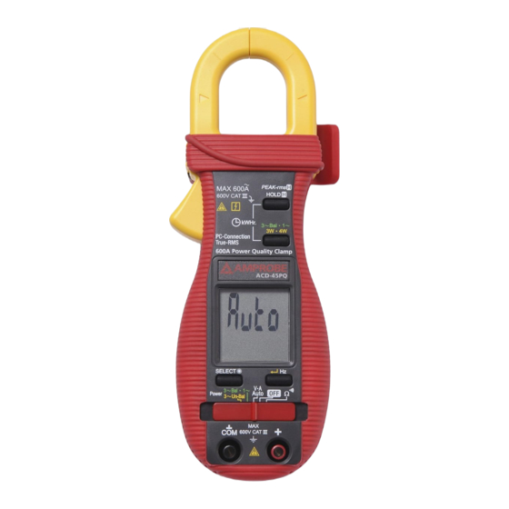
- Page 6 ACD-45PQ 600A Power Quality Clamp Transformer Clamp Jaws for AC current magnetic field pick up Jaw marking lines for ACA (& thus Power) position error indication Hand/Finger Barrier to indicate the limits of safe access to the jaws during current...
- Page 7 ACD-45PQ 600A Power Quality Clamp .......................1 ................3 ......................3 AutoVA Function ..................4 Peak-rms Mode ....................5 Line-level Frequency (Hz) Function ..............5 HOLD Mode ....................6 Single-Phase Power & 3-Phase Balanced-Load Power Functions ....8 kWHr (kilo-Watt-Hour) Recording Function ............9 3-Phase 3-Wire (3 3W) Unbalanced-Load Power Function ......11 3-Phase 4-Wire (3 4W) Unbalanced-Load Power Function ......12...
- Page 8 � Caution! Risk of electric shock � Caution! Refer to the explanation in this Manual � Double Insulation or Reinforced insulation � Alternating Current (AC). � Direct Current (DC). � Fuse � Earth (Ground) Please remove all the test leads before preforming maintenance, �...
- Page 9 is for measurements performed in the building installation. Examples are measurements on distribution boards, circuit- breakers, wiring, including cables, bus-bars, junction boxes, switches, socket-outlets in the fixed installation, and equipment for industrial use and some other equipment, for example, stationary motors with permanent connection to the fixed installation.
- Page 10 Your shipping carton should include: 1 ACD-45PQ 600A Power Quality Clamp 1 Test Leads (Black x 1; Red x 1) 1 Bag 1 Users Manual 2 1.5V AAA LR03/NEDA 24A Batteries (Installed) If any of the items are damaged or missing, return the complete package to the place of purchase for an exchange.
- Page 11 Set the slide-switch function-selector to the position. ” when it is ready. nominal threshold of DC 2.4V or AC 30V (40Hz ~ 500Hz) up to the rated 600V is present on V-COM terminals, the meter displays the voltage value in appropriate DC or AC, whichever larger in peak magnitude. Annunciators “...
- Page 12 Peak-rms compares and displays the maximum RMS value of surge voltage or current with durations as short as 65ms. When ACV or ACA function is auto- selected or manual-selected, press and hold Peak-rms button for one second or more toggles to this mode. The annunciators “ ” “ ”...
- Page 13 In ACA function, activating the Hz function during significant measurements can get the most appropriate trigger level to avoid electrical noises in most cases. Activating the Hz function at AC 40.00A range (before making significant measurements) can get the lowest trigger level (highest sensitivity). When any function is auto-selected or manual-selected, press HOLD button momentarily toggles to Hold mode.
- Page 14 power factor, is no longer the only component constituting the overall power factor. Harmonics do increase apparent power and thus decrease the overall power factor. That is the Total Power Factor is actually affected by both phase-shift angle and harmonics, and is given by the expression: In order to improve overall system power factor, nowadays power-system engineer needs to address both phase-shift and harmonics problems.
- Page 15 Set the slide-switch function-selector to the “ ” Power position. ” button momentarily to toggle between “ ” and “ ” Power functions. Annunciators “ ” and “ ” turn on respectively. (reactive power), VA (apparent power) & kWHr (real-time readings or stored result) functions.
- Page 16 1. Under proper measurement setups for load circuits, the W (real power) readings are always positive. Negative W readings indicate reversed clamp-on jaws direction or test leads polarities, or even incorrect voltage lines are being measured as in 3-phase measurement setups. Correct them for proper “A-lags-V”...
- Page 17 Set the slide-switch function-selector to the “ ” Power position. Setup power measurements as mentioned in the previous “ ” section ”) kWHr Recording, press “ ” and “ ” buttons at the same time. Annunciator “ ” turns on & flashes. kWHr accumulated time (in Hour) is displayed automatically in the secondary mini display.
- Page 18 ”) properly, the new result will supersede the previous one stored in the non-volatile memory. You can then switch off the meter for transportation, storage, or even battery changing with memory remained. ”) kWHr Recording session before sliding the slide-switch function-selector to any other function positions.
- Page 19 ” Power position. Press “ ” button momentarily to select 4-Wire measurements. Annunciator “ ” turns on. ” as reminded by annunciators “ ”, and connect Black test probe (COM terminal) to “ ” and Red test probe (+ terminal) to “ ”...
- Page 20 ” as reminded by annunciators “ ”, and connect Black test probe (COM terminal) to “ ” and Red test probe (+ terminal) to “Line 3” as reminded by annunciators “ ” on mini-display. ” button momentarily to enter the third measuring value.
- Page 21 � Set the slide-switch function-selector to the � function position. Default at last selected function. Press SELECT button to toggle between � and measurement functions. Press the SELECT button for 1 second or more to toggle the display backlight on or off. The meter turns off after approximately 30 minutes of neither switch nor button activity.
- Page 22 Press-and-hold the 3W.4W button while powering the meter on. The LCD displays “ ” & “ ” to confirm activation right after the 3W.4W button is released. Quick test APO timing is 10 seconds after such activation. Press-and-hold the HOLD button while powering the meter on. The LCD displays “...
- Page 23 6000 counts LCD display Power 9999 counts LCD display 4000 counts LCD display 2 per second nominal Voltage, 2 per second nominal 1 per second nominal Automatic Below approx. 2.4V 0˚C to 40˚C (32˚ to 104˚F) Maximum relative humidity 80% for temperature up to 31˚C (88˚F) decreasing linearly to 50% relative humidity at 40˚C (104˚F) Operating below 2000m...
- Page 24 Meets EN61326-1:2006 (EN55022, EN61000- 3-2, EN61000-3-3, EN61000-4-2, EN61000-4-3, EN61000-4-4, , EN61000-4-5, EN61000-4-6, EN61000-4-8, EN61000-4-11) Total Accuracy = Specified Accuracy + 50 digits Performance above 3V/m is not specified AC 600A rms continuous 600VDC/ VAC rms standard 1.5V AAA Size (NEDA 24A or IEC LR03) battery X 2 11mA typical...
- Page 25 True RMS ACV & ACA clamp-on accuracies are specified from 0% to 100% of range or otherwise specified. Maximum Crest Factor are as specified below, and with frequency spectrums, besides fundamentals, fall within the meter specified AC bandwidth for non-sinusoidal waveforms. Fundamentals are specified at 50Hz and 60Hz.
- Page 26 40.00A, 400.0A, 600A 1.0% + 5d 40.00A, 400.0A 2.0% + 5d 600A 2.5% + 5d 40.00A, 400.0A 2.5% + 5d 600A 3.0% + 5d 1A AC (40Hz ~ 500Hz only) nominal < 3 : 1 at full scale & < 6 : 1 at half scale for 40.00A, 400.0A & 600A ranges 1.
- Page 27 5Hz ~ 500Hz 0.5%+4d 0.4VDC typical between 10� and 300�. 250µs 2.0%+6d 3.5%+6d 5.5%+6d 2.0%+6d 0.70 3.5%+6d 3.0%+6d 4.5%+6d 10%+6d 0.50 4.5%+6d 10%+6d 15%+6d 0.20 1. Specified accuracy is for ACA clamp measurement at the center of jaws. When the conductor is not positioned at the jaw center, position errors introduced are: jaw marking lines (away from jaw opening) marking lines (toward jaws opening)
- Page 28 2. Add 4d to specified accuracy for 3-Phase Balanced-Load Power measurements. 3. Add 1% to specified accuracy @ ACA fundamental < 6A or ACV fundamental < 90V. Accuracy is not specified @ ACA fundamental < 1A or ACV fundamental < 30V 4.
- Page 29 �WARNING To avoid electrical shock, disconnect the meter from any circuit, remove the test leads from the input jacks and turn OFF the meter before opening the case. Do not operate with open case. If the instrument fails to operate, check batteries and test leads etc., and replace as necessary.
- Page 30 The meter uses standard 1.5V AAA Size (NEDA 24A or IEC LR03) battery X 2 Loosen the 2 captive screws from the battery cover case. Lift the battery cover case. Replace the batteries. Replace battery cover case. Re-fasten the screws.
Need help?
Do you have a question about the ACD-45PQ and is the answer not in the manual?
Questions and answers