
Subscribe to Our Youtube Channel
Related Manuals for Smithco SweepStar 48


Summary of Contents for Smithco SweepStar 48
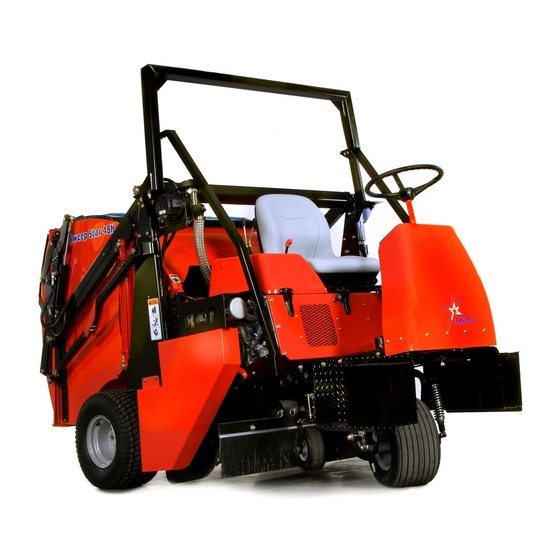
- Page 1 Parts & Service SweepStar 48 48-000-C SN: GH5156 November 2010 Product Support: Hwy SS & Poplar Ave; Cameron WI 54822 1-800-891-9435 productsupport@smithco.com...
-
Page 2: Table Of Contents
CONTENTS Introduction .......... 1-10 Introduction ....................1-3 Safe Practices ..................2 Specification ..................... 3 Optional Equipment .................. 3 Service ..................... 4-10 Maintenance ..................4-6 Service Chart .................... 7 End User’s Service Chart ................8 Adjustments ..................... 9 Storage ..................... 9 Reel Height Adjustment ................ -
Page 3: Introduction
INTRODUCTION Thank you for purchasing a product. Read this manual and all other manuals pertaining to the Sweep Star 48 carefully as they have safety, operat- ing, assembly and maintenance instructions. Failure to do so could result in personal injury or equipment dam- age. -
Page 4: Safe Practices
19. Stop engine before making repairs/adjustments or checking/adding oil to the crankcase. 20. Use parts and materials supplied by SMITHCO only. Do not modify any function or part. 21. Do not remove the radiator cap when the engine is hot. When cooled, loosen cap slightly to the stop to relieve any pressure before removing the cap completely. -
Page 5: Specification
SPECIFICATIONS FOR SWEEP STAR 48 HIGH LIFT WEIGHTS AND DIMENSIONS HIGH LIFT Length 121" (307 cm) Width 60" (153 cm) Height with Hopper Down 63" (160 cm) Height with Hopper Up 126" (320 cm) Wheel Base 70" (179 cm) Weight 1900 lbs(862 kg) SOUND LEVEL (DBA) At ear level... -
Page 6: Maintenance
MAINTENANCE Before servicing or making adjustments to machine, stop engine and remove key from ignition. Use all procedures and parts prescribed by the manufacturer's. Read the engine manual. LUBRICATION Use No. 2 General Purpose Lithium Base Grease and lubricate every 100 hours. The Sweep Star 48 has eleven grease fittings. - Page 7 MAINTENANCE (CONTINUED) TIRE PRESSURE Caution must be used when inflating a low tire to recommended pressure. Over inflating can cause tires to explode. Front and rear tires and castor wheel should be 20 psi (1.4bar) maximum. Improper inflation will re- duce tire life considerably.
- Page 8 MAINTENANCE (CONTINUED) BATTERY Batteries normally produce explosive gases which can cause personal injury. Do not allow flames, sparks or any ignited object to come near the battery. When charging or working near battery, always shield your eyes and always provide proper ventilation. Battery cable should be disconnected before using “Fast Charge”.
-
Page 9: Service Chart
SERVICE CHART Before servicing or making adjustments to the machine, stop engine, set park break, block wheels and remove key from ignition. Follow all procedures and ONLY use parts prescribed by the manufacturer. Read the engine manual before maintenance. The suggested maintenance checklist is not offered as a replacement for the manufacturer’s engine manual but as a supplement. -
Page 10: End Users Service Chart
END USERS SERVICE CHART Duplicate this page for routine use. For the week of: Maintence Check Item Tues. Wed. Thurs. Fri. Sat. Sun. Check the Safety Seat Switch Check Steering Operation Check the fuel level Check the engine oil level. Check the condition of the air filter Clean the engine cooling fins. -
Page 11: Adjustments
ADJUSTMENTS PARK BRAKE ADJUSTMENT By turning knob on end of park brake lever you can tighten or loosen brake a small amount. To tighten turn the knob clockwise. To loosen turn counter clockwise. If this is not enough turn clevis on the rear of the brake cable to adjust length of cable. -
Page 12: Reel Height Adjustment
REEL HEIGHT ADJUSTMENT Below are the various ways that the Sweep Star 48 castor wheels can be adjusted to accommodate for the fin- ger/brush reel height. By changing the two spacers around on the castor wheel fork you can experience a range of ground clearances on the finger/brush reel. - Page 13 NOTES...
-
Page 14: Wiring Diagram
WIRING DIAGRAM Color Code Chart Blue Brown Yellow Green Orange Black Purple... - Page 15 WIRING DIAGRAM PARTS LIST REF# PART# DESCRIPTION QUANTITY 22-003 Ammeter 76-269 Power Wire to Hour Meter 12-017 Hour Meter 76-259 Ground Wire for Hour Meter 77-209 Ground Wire for Ignition Switch 34-146 Panel Mount Circuit Breaker 34-145 Circuit Breaker Boot 13-288 Key Switch with Hardware (Kohler #25 099 04)
-
Page 16: Hydraulic Diagram High Lift
HYDRAULIC DIAGRAM (HIGH LIFT) 76-023 3-Bank Hydraulic Valve Relief Valve set at 2000 PSI(137.93 Bar) 76-322 Hydrostat Pump Displacement Variable to .913 in /R(15 cc 14.23 GPM(53.85LPM) at 3600 RPM Max Operating Speed 3600 RPM Rated Pressure 3000 PSI(206.8 Bar) Max Pressure 4500 PSI(310 Bar) Max Inlet Vacuum... -
Page 17: Parts
HYDRAULIC DIAGRAM PARTS LIST (HIGH LIFT) REF# PART# DESCRIPTION QUANTITY 76-242 Hydraulic Cylinder 48-012 Hydraulic Hose 48-013 Hydraulic Hose 48-137 Wheel Motor 34-057 48-015 Hydraulic Hose 8810-19 Hose 18-077 Hose Clamp 8895-22 Hose Wrap 22" 48-016 Hydraulic Hose 8895-44 Hose Wrap 44" 76-322 Hydrostatic Pump 76-323... - Page 18 BODY AND FRAME DRAWING...
- Page 19 BODY AND FRAME PARTS LIST REF# PART# DESCRIPTION QUANTITY 60-130 Tire and Wheel 60-130-01 Tire 18 x 9.5 x 8 60-130-02 Wheel 48-158 Front Cover HB-14-20-075 Bolt - 20 x HW-14 Washer HNFL-14-20 Flange Whiz Lock Nut 48-161 Left Step 48-173 Main Frame 48-159...
- Page 20 ROLL OVER PROTECTION DRAWING...
- Page 21 ROLL OVER PROTECTION PARTS LIST REF# PART# DESCRIPTION QUANTITY HB-38-16-100 Bolt, - 16 x 1 HWL-38 Lock Washer, - 16 48-210 Left Support Bar HB-12-13-300 Bolt, -13 x 3 HNTL-12-13 Lock Nut, HB-38-16-100 Bolt, - 16 x 1 HNTL-38-16 Lock Nut, HB-12-13-125 Bolt, -13 x 1...
-
Page 22: Steering
STEERING DRAWING... -
Page 23: Front Fork
STEERING PARTS LIST REF# PART# DESCRIPTION QUANTITY 48-186 Steering Shaft HWK-316-075 Woodruff Key 76-362 Tilt Steering Mechanism 76-364 Tilt Steering Boot (comes with 76-362) 13-718 Steering Wheel 13-726 Steering Wheel Cap HNJ-58-18 Jam Nut - 18 75-833 Universal Joint HSSHS-516-18-038 Socket Head Set Screw - 18 x 75-813... - Page 24 FRONT FORK DRAWING...
- Page 25 FRONT FORK PARTS LIST REF# PART# DESCRIPTION QUANTITY HW-38 Washer (as Req'd) HB-38-16-200 Bolt - 16 x 2 HNTL-38-16 Locknut - 16 HB-38-16-250 Bolt - 16 x 2 HNTL-38-16 Locknut - 16 75-715 Shock Absorber 75-864 Bushing 2 per shock (comes with shock) HN-38-16 - 16...
- Page 26 LINKAGE DRAWING...
- Page 27 LINKAGE PARTS LIST REF# PART# DESCRIPTION QUANTITY HB-38-16-250 Bolt - 16 x 2 HNTL-38-16 Lock Nut - 16 48-026 Seat Panel 48-163 Filter Bracket HB-516-18-300 Bolt - 18 x 3 HW-516 Washer HNTL-516-18 Lock Nut - 18 15-013 Rubber Bumper 48-056 Seat Support 34-038...
- Page 28 CONSOLE DRAWING...
- Page 29 CONSOLE PARTS LIST REF# PART# DESCRIPTION QUANTITY 34-146 Panel Mount Circuit Breaker 34-145 Circuit Breaker Boot 12-017 Hour Meter 22-003 Ammeter 13-288 Key Switch (with hardware Kohler# 25 099 04) 76-310 Key Set 34-160 Throttle 48" 34-159 Throttle Mounting Bracket HSM-10-32-063 Machine Screw 10 - 32 x HWL-10...
- Page 30 FUEL AND OIL TANK DRAWING 60-213 Strainer...
- Page 31 FUEL AND OIL TANK PARTS LIST REF# PART# DESCRIPTION QUANTITY 15-838 CARB Gas Tank (includes all * items) Neck Vent Port 8800-48 Fuel Hose (tank to carb canister) 18-186 Hose Clamp 8832-19 " Hose 18-040 Clamp HB-516-18-100 Bolt - 18 x 1 HW-516 Washer HWL-516...
-
Page 32: Hydraulic Lift Cylinder
HYDRAULIC LIFT CYLINDER DRAWING INCLINOMETER DRAWING... - Page 33 HYDRAULIC LIFT CYLINDER PARTS LIST REF# PART# DESCRIPTION QUANTITY 76-242 Hydraulic Cylinder 76-242-01 Seal Kit 23-167 Elbow 76-242-02 Clevis pin with Clip INCLINOMETER PARTS LIST REF# PART # DESCRIPTION QUANTITY HSM-8-32-075 Machine Screw #8 -32 x HNFL-8-32 Flange Whiz Lock Nut #8 -32 76-373 Inclinometer Bracket HSM-8-32-100...
-
Page 34: Reel Lift Cylinder
REEL LIFT CYLINDER DRAWING TAILGATE CYLINDER DRAWING... - Page 35 REEL LIFT CYLINDER PARTS LIST REF# PART# DESCRIPTION QUANTITY 18-168 Elbow HP-18-100 Cotter Pin HCP-12-350 Clevis Pin 76-478 Hydraulic Cylinder 14-531 Seal Kit TAILGATE CYLINDER PARTS LIST REF# PART# DESCRIPTION QUANTITY HHP-18 Bridge Pin 18-168 Elbow 15-839 Hydraulic Cylinder 14-531 Seal Kit HNJ-58-18 Jam Nut...
- Page 36 ENGINE AND EXHAUST DRAWING...
- Page 37 ENGINE AND EXHAUST PARTS LIST REF# PART# DESCRIPTION QUANTITY 23-184 Male Connector 18-161 Straight Thread Elbow 23-139 Barb Fitting 23-133 Elbow 76-322 Hydrostatic Pump HSSH-12-13-175 Socket Set Screw - 13 x 1 HWL-12 Lock Washer 48-213 Rear Engine Guard HSTP-14-20-100 Phillips Truss Head Machine Screw - 20 x 1 HW-14...
- Page 38 ENGINE AND EXHAUST DRAWING...
- Page 39 ENGINE AND EXHAUST PARTS LIST REF# PART# DESCRIPTION QUANTITY 48-169 Front Cooler Bracket HB-516-18-100 Bolt -18 x 1 HNTL-516-18 Lock Nut - 18 48-192 Engine Mount 23-127 Elbow 48-196 Shift Arm 8946-1 Plastic Wear Strip HRS-316-050 Rivet HRP-14-100 Roll Pin 76-323 Gear Pump (replacement only;...
- Page 40 ELECTRIC CLUTCH DRIVEN BELT DRIVE & MUFFLER DRAWING...
- Page 41 ELECTRIC CLUTCH DRIVEN BELT DRIVE & MUFFLER PARTS LIST REF# PART# DESCRIPTION QUANTITY 48-038 Spring Bracket HMB-100-10 Machine Bushing 1 x 10GA 21-445 Spring 76-337 Electric Clutch 17-271 Pigtail 16-013 Idler Pulley 76-217 Idler Arm 76-298 Spacer HB-12-13-300 Bolt - 13 x 3 HNTL-12-13 Lock Nut - 13...
- Page 42 FINGER / BRUSH REEL DRAWING...
- Page 43 FINGER / BRUSH REEL PARTS LIST REF# PART# DESCRIPTION QUANTITY HB-34-10-550 Bolt - 10 x 5 33-435 Tire and Wheel HNTL-34-10 - 10 48-046 Castor Fork 29-585 Spacer Height Adjustment 1" 18-223 Bushing (part of 77-171) 77-171 HG-14-28-180 Grease Fitting - 28 x 180°...
- Page 44 REAR AXLE DRAWING...
- Page 45 REAR AXLE PARTS LIST REF# PART# DESCRIPTION QUANTITY 34-122 Short Elbow 76-240 Left Caliper 11-100 Linkage Yoke 76-300 Brake Rod HN-516-24 - 24 21-462 Ball Joint - 24 60-347 Brake Cable 60-536 Bellows 48-006 Rear Beater Panel 48-173 Main Frame 48-029 Grass Chute 8947-48...
- Page 46 HOPPER AND TAILGATE DRAWING 48-120 Dust and Filtration Pack for High Lift 48-064 Hopper Filter 24" x 44" 48-065 Tailgate Filter 17" x 50"...
- Page 47 HOPPER AND TAILGATE PARTS LIST REF# PART# DESCRIPTION QUANTITY 48-005 Tailgate 48-023 Tailgate Screen 48-037 Left Dump Arm HNA-100-14 Castle Nut 1 - 14 48-153 Left Adjustment Sleeve 48-061 Hopper Dump Arm 75-653 Hopper Safety Lift ( not pictured) HB-38-16-225 Bolt - 16 x 2 HNW-38-16...
-
Page 48: 76-322 15 Series Sundstrand Pump
76-322 15 SERIES SUNDSTRAND PUMP DRAWING NOTE: #8 is Gage Port... - Page 49 76-322 15 SERIES SUNDSTRAND PUMP PARTS LIST REF# PART# DESCRIPTION QUANTITY 42-003-01 O-Ring 14-130 Ring 13-110-01 By-Pass Valve 14-115 Valve Plate 42-003-16 Cylinder Block Kit 76-322-02 Pump Shaft 13-110-05 Pipe Plug 14-069 Needle Bearing 42-003-04 Lip Seal 42-003-05 Washer 14-212 Truncated Shaft (short 1 holes) 14-105 Retaining Ring...
-
Page 50: 48-137 Rear Wheel Motor
48-137 REAR WHEEL MOTOR (10.3 C.I.) DRAWING... - Page 51 48-137 REAR WHEEL MOTOR (10.3 C.I.) PARTS LIST REF# PART# DESCRIPTION QUANTITY Water & Dirt Seal 13-615-05 Service Housing Assembly (includes #4,5,17(2 Req'd) and 20) Inner Seal 13-032-27 Thrust Bearing 13-032-28 Inner Bearing 13-032-29 Thrust Bearing 48-137-01 Drive Link Ring Seal 13-032-31 Manifold 13-032-32...
- Page 52 76-023 3 -BANK HYDRAULIC VALVE DRAWING...
- Page 53 76-023 3 -BANK HYDRAULIC VALVE PARTS LIST REF# PART# DESCRIPTION QUANTITY 76-023-03 Mounting Bracket HN-516-18 Hex Nut - 18 HW-14 Washer 76-023-06 Tie Rod 18-168 Elbow 90° 18-202 Elbow 90° Linkage (comes with handle) 76-309 Valve Handle (sold as a set of 3) 76-023-07 Body and Spool (matching set)
-
Page 54: Notes
NOTES... -
Page 55: Decal List
Hang Tag 25-356 Tire Pressure (20 psi) All Wheels 25-362 Decal, Danger Fire Hopper Front 27-093* Hydraulic Oil Console Back 34-147 Smithco Star Hopper Sides 48-145 Sweep Star 48 H Hopper Sides 25-374 Smithco Tailgate 25-375 94 dBA Seat Panel... -
Page 56: Quick Reference Replacement Parts
QUICK REFERENCE REPLACEMENT PARTS REPLACEMENT FILTERS 48-083-01 Hydraulic Oil Filter (High Dump) 78-090 Oil Filter Kohler# 12 050 01 76-311 Air Element 48-000 Kohler#24 083 03 76-312 Pre-Cleaner 48-000 Kohler#24 083 05 50-403 Fuel Filter for Kohler REPLACEMENT BELTS 76-200 Finger Reel Belt 2/A74 SEAL KITS 76-023... -
Page 57: Warranty
January 1, 2007, to be free from defects in materials or workmanship for the period of time listed below. Where a warrantable condition exists, Smithco will repair the Product at no cost to you including diagnosis, labor (at the Smithco standard labor rate, subject to the Smithco flat rate schedule), and parts. - Page 58 Smithco may require the return of failed parts or components in order to determine the validity of any warranty claim. Smithco will not be obligated to replace components of other manufacturers if inspection by the original component manufacturer indicates that failure was due to normal wear and tear, expected consumption through use or improper care or service.
Need help?
Do you have a question about the SweepStar 48 and is the answer not in the manual?
Questions and answers