Sign In
Upload
Download
Table of Contents
Contents
Add to my manuals
Delete from my manuals
Share
URL of this page:
HTML Link:
Bookmark this page
Add
Manual will be automatically added to "My Manuals"
Print this page
×
Bookmark added
×
Added to my manuals
Manuals
Brands
Shimano Manuals
Bicycle
GRX RD-RX810
Dealer's manual
Shimano GRX RD-RX810 Dealer's Manual
Hide thumbs
1
Table Of Contents
2
3
4
5
6
7
8
9
10
11
12
13
14
15
16
17
18
19
20
21
22
23
24
25
26
27
28
29
30
31
32
33
34
35
36
37
page
of
37
Go
/
37
Contents
Table of Contents
Bookmarks
Table of Contents
Table of Contents
Contents
Important Notice
To Ensure Safety
List of Tools to be Used
Installation/Removal
Installing the Rear Derailleur
Standard Type
Direct Mount Type
Adjustment
Adjusting the Stroke on the High Limit
Installing the Chain
Checking the Chain Length
Connection and Securing of the Inner Cable
Outer Casing Length
Connection and Securing of the Inner Cable
Adjusting the Stroke on the Low Limit
Adjusting the B-Screw
SIS Adjustment
Maintenance
Replacing the Pulleys
Applying Grease to the Chain Stabilizer
Adjusting Friction
Replacement of the Plate and the Plate Tension Spring
Removal
Installation
Advertisement
Quick Links
1
Table of Contents
2
Installing the Rear Derailleur
3
Installation/Removal
4
Adjusting the Stroke on the High Limit
5
Adjustment
6
Adjusting the Stroke on the Low Limit
7
Adjusting the B-Screw
Download this manual
(English)
ROAD
City Touring/
Comfort Bike
GRX
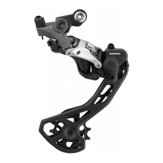
RD-RX810
RD-RX812
RD-RX400
URBAN SPORT
Rear Derailleur
Dealer's Manual
MTB
DM-GARD001-02
Trekking
E-BIKE
Table of
Contents
Previous
Page
Next
Page
1
2
3
4
5
Advertisement
Table of Contents
Need help?
Do you have a question about the GRX RD-RX810 and is the answer not in the manual?
Ask a question
Questions and answers
Related Manuals for Shimano GRX RD-RX810
Bicycle Shimano GRX RD-RX812 Dealer's Manual
(37 pages)
Bicycle Shimano GRX RD-RX400 Dealer's Manual
(37 pages)
Bicycle Shimano Ultegra 6770 Series Manuals
(24 pages)
Bicycle Shimano STEPS E6000 User Manual
Shimano steps e6000 battery and charger (46 pages)
Bicycle Shimano EP801 User Manual
(30 pages)
Bicycle Shimano NEXUS SG-C7002-5 Dealer's Manual
(48 pages)
Shimano Steps E6000 Series Manual
(article)
Bicycle Shimano EDISON COMP I-12 Original Operating Instructions
(257 pages)
This manual is also suitable for:
Grx rd-rx812
Grx rd-rx400
Table of Contents
Save PDF
Print
Rename the bookmark
Delete bookmark?
Delete from my manuals?
Login
Sign In
OR
Sign in with Facebook
Sign in with Google
Upload manual
Upload from disk
Upload from URL


Need help?
Do you have a question about the GRX RD-RX810 and is the answer not in the manual?
Questions and answers