
Related Manuals for Citizen MLT-288


Summary of Contents for Citizen MLT-288
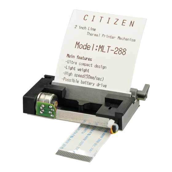
- Page 1 Service Manual LINE THERMAL PRINTER MECHANISM MLT-288 MODEL Rev.1.00 Newly issued on Sep. 29, 2000...
- Page 2 REVISION Rev.No. Date Comment Rev.1.00 Sep. 29, 2000 Newly issued...
- Page 3 MLT-288, and is intended for maintenance personnel in fields. Characteristics MLT-288 is a line dot type small-sized printer provided with a line thermal head. This printer has been developed for the output terminals for POS terminals, measuring and analyzing equipment, medical equipment, communication data equipment, and the like, and is small-sized as far as possible.
-
Page 4: Table Of Contents
CONTENTS Chapter 1 Handling and Maintenance of Printer.................. 1 Chapter 2 Specifications and Principle of Operation................2 2-1 General Specifications ..........................2 2-2 Outline of Mechanism ........................... 3 2-3 Mechanism and Operational Principle ......................3 2-3-1 Power Transmission Mechanism Block ....................4 2-3-2 Sensor Mechanism Block ........................ -
Page 5: Chapter 1 Handling And Maintenance Of Printer
MLT-288 Service Manual Chapter 1 Handling and Maintenance of Printer (1) The use of paper other than our recommended paper can not guarantee print quality and duration. Be sure to use paper with a width within the specified range. (2) Do not give the surface of the head circuit board (heating elements) a mechanical shock (including penetration of foreign matters). -
Page 6: Chapter 2 Specifications And Principle Of Operation
MLT-288 Service Manual Chapter 2 Specifications and Principle of Operation 2-1 General Specifications Item Specifications Remarks Printing Method Thermal Line Dot Method Total number of dot 384 dots/line Dot density 8 dots/mm Printing width 48.0 mm Printing Speed 200 dot lines/second 5V, Head temp.≥50°C,≤64 dots... -
Page 7: Outline Of Mechanism
MLT-288 Service Manual 2-2 Outline of Mechanism The mechanism of this printer is roughly separated into the following six blocks. * Power transmission mechanism block. * Sensor mechanism block. * Print head mechanism block. * Paper feed mechanism block. * Frame block. -
Page 8: Power Transmission Mechanism Block
MLT-288 Service Manual 2-3-2 Sensor Mechanism Block This sensor mechanism block is composed of a head-up and paper sensors. (1) Head-up sensor This is a sensor to detect a head up/down condition. Activating the head in the head-up condition is likely to damage the head or decrease the duration significantly. -
Page 9: Sensor Mechanism Block
MLT-288 Service Manual 2-3-3 Print Head Mechanism Block A thermal head is used as the print head of this printer. The thermal head is composed of heating elements and a head driver to drive and control the elements. (1) Outline of drive control Serial print data input from SI are transferred to the shift register in synchronization with CLOCK and stored in the latch register by the LATCH signal. - Page 10 MLT-288 Service Manual (2) Head separation processing There are six thermal head strobes. The relationship between the strobe and heating element positions are as follows: STB No. Elements No. Number of dots /STB 1~64 65~128 129~192 193~256 257~320 321~384 (3) Print data and print location Data No.
-
Page 11: Print Head Mechanism Block
MLT-288 Service Manual (4) Up/Down mechanism of print head The print head is normally held in the down condition. When the head-up lever is pushed up, the cam of the lever rotates to push heat sink up and to separate the thermal head from the platen to put the thermal head in the up condition. -
Page 12: Connecting Terminal
MLT-288 Service Manual 2-4 Connecting Terminal The connecting terminal is composed of two connectors. Details are described in the following. Function Number of pins Type Recommended mated connector Thermal head FFC Cable 52806-2410 (Pitch: 1mm) (Molex) “Head up” sensor 51021-0900... -
Page 13: Motor And Sensor Connector
MLT-288 Service Manual 2-4-2 Motor and Sensor connector The pin layout of the each sensors and motor connector and the name of each pin are as follows. Pin layout of motor and sensors connector Pin No. Pin name Remarks Motor... -
Page 14: Chapter 3 Disassembling And Reassembling
MLT-288 Service Manual Chapter 3 Disassembling and Reassembling Pay attention to the following matters in maintenance work Caution: (1) Do not disassemble, reassemble, nor adjust the printer without reasons, if it works normally. Do not undo carelessly screws for fixing components in particular. -
Page 15: Procedure For Reassembling Printer Body
MLT-288 Service Manual 3-3-1 Procedure for Reassembling Printer Body (1) Incorporate the motor assembly to the frame assembly. (2) Fix the motor assembly to the frame assembly by a fitting screw (M2 x 3). Frame ASSY Rear Mounting screw (M2x3) Motor ASSY (3) Incorporate the head-up sensor to the right side of the frame assembly. - Page 16 MLT-288 Service Manual (4) Incorporate the paper sensor to the bottom surface of the frame assembly. Caution: Be careful not to break the cover of lead wires in incorporating work. Paper sensor Rear (5) Fix lead wires for the motor assembly with binding strap for lead wires not to get loose.
- Page 17 MLT-288 Service Manual (6) Apply furoyl G-943 to the three gear pivots on the left side of the frame assembly and to the 5 platen insert Ø hole. Rear 5 platen insert hole Ø Gear pivods (7) Assemble the platen in the frame assembly.
- Page 18 MLT-288 Service Manual (8) Incorporate the 1st reduction gear so that it may engage with the gear of the motor. Incorporate the 2nd reduction gear so that it may engage with the 1st reduction gear. Caution: In incorporating, be careful about the direction so that the smaller gear comes to the upper side.
- Page 19 MLT-288 Service Manual (10) Insert the head SP assembly from the frame assembly top surface and insert the two holes for the head SP assembly into the projection at the bottom of the frame assembly. Caution on Handling Thermal Head Assembly: Do not touch the print surface of the head with bare hands.
-
Page 20: Head Sp Assy Reassembling Procedure
MLT-288 Service Manual (12) Insert the mounting screw (M1.7 x 8) into the mounting hole for the motor on the left side of the frame assembly and secure the motor. Rear Frame ASSY Mounting screws (M1.7x8) This is the end of reassembling work of the printer body. -
Page 21: Chapter 4 Trouble-Shooting
MLT-288 Service Manual Chapter 4 Trouble-Shooting 4-1 Procedure for Repairs When the printer is out of order, observe the phenomenon of the trouble carefully to specify what is the trouble according to 4-2 “Guide to Repairs.” Then, repair it according to the prescribed method. -
Page 22: Guide To Repair
MLT-288 Service Manual 4-2 Guide to Repair 4-2-1 Guide to repair Phenomenon Cause Check method Repair method Power supply to head poor. Measure power supply voltage If out of rating, correct with tester or oscilloscope. power supply circuit. Print impossible... -
Page 23: Guide To Repair
MLT-288 Service Manual 4-2-2 Guide to repair Phenomenon Cause Check method Repair method Motor connector (Terminal) Check connected condition of Connect connector connection poor connector. correctly. Paper feed motor Power supply to motor Measure power supply voltage If out of rating, correct... -
Page 24: Chapter 5 Parts List
MLT-288 Service Manual Chapter 5 Parts List MLT-288 Q’ ty Ref. No. Parts No. Description Remarks 100091-00 FRAME ASSY 600300-00 FRAME 500277-00 CHASSIS 800396-00 PLATEN 600301-00 HEADUP LEVER 600302-00 REDUCTION GEAR 1 600303-00 REDUCTION GEAR 2 600304-00 REDUCTION GEAR 3... -
Page 25: Chapter 6 Disassemble Drawing
MLT-288 Service Manual Chapter 6 Disassemble Drawing MLT-288 disassemble drawing...
Need help?
Do you have a question about the MLT-288 and is the answer not in the manual?
Questions and answers