Vega VEGAMET 624 Operating Instructions Manual
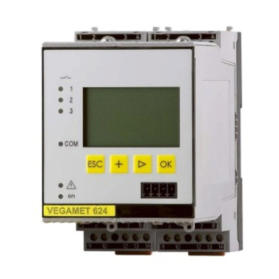
Controller and display instrument for level sensors
Hide thumbs
Also See for VEGAMET 624:
- Supplementary instructions manual (64 pages) ,
- Operating instructions manual (60 pages) ,
- Supplementary instructions manual (40 pages)

Related Manuals for Vega VEGAMET 624


Summary of Contents for Vega VEGAMET 624
- Page 1 Operating Instructions Controller and display instrument for level sensors VEGAMET 624 4 … 20 mA/HART Document ID: 28969...
-
Page 2: Table Of Contents
Flow measurement ......................41 Diagnostics and servicing ....................44 Maintenance ........................44 Rectify faults ........................44 Diagnosis, fault messages ..................... 44 How to proceed if a repair is necessary ................46 10 Dismount..........................48 VEGAMET 624 • 4 … 20 mA/HART... - Page 3 12.2 Overview applications/functionality ................53 12.3 Dimensions ........................54 12.4 Industrial property rights ....................55 12.5 Trademark ........................55 Supplementary documentation Information: Supplementary documents appropriate to the ordered version come with the delivery. You can find them listed in chapter " Product descrip- tion". Editing status: 2021-06-10 VEGAMET 624 • 4 … 20 mA/HART...
-
Page 4: About This Document
Symbols used Document ID This symbol on the front page of this instruction refers to the Docu- ment ID. By entering the Document ID on www.vega.com you will reach the document download. Information, note, tip: This symbol indicates helpful additional infor- mation and tips for successful work. -
Page 5: For Your Safety
During work on and with the device, the required personal protective equipment must always be worn. Appropriate use VEGAMET 624 is a universal controller for connection of a 4 … 20 mA sensor. You can find detailed information about the area of application in chapter " Product description". Operational reliability is ensured only if the instrument is properly used according to the specifications in the operating instructions manual as well as possible supplementary instructions. -
Page 6: Installation And Operation In The Usa And Canada
Safety instructions for Ex areas For applications in explosion-proof areas (Ex), only devices with cor- responding Ex approval may be used. Observe the Ex-specific safety instructions. These are an integral part of the operating instructions and are enclosed with every device with Ex approval. VEGAMET 624 • 4 … 20 mA/HART... -
Page 7: Product Description
– Supplementary instructions manual 30768 " Modbus-TCP, VEGA ASCII protocol" (optional) – Ex-specific " Safety instructions" (with Ex versions) – If necessary, further certificates Constituent parts The VEGAMET 624 consists of the components: • VEGAMET 624 controller with display and adjustment unit in the front • Terminal socket Ser. No. VEGAMET 12345678 9 10... -
Page 8: Principle Of Operation
At the same time, it can serve as power supply unit for connected sensors. VEGAMET 624 is designed for connection of any 4 … 20 mA/HART sensor. On instruments with one of the optional interfaces (RS232/Ethernet), the measured values can be retrieved via modem or network and displayed by means of a web browser or VEGA Inventory System. -
Page 9: Packaging, Transport And Storage
3 Product description Further instructions for setting up the web server and e-mail functions can be found in the online help of PACTware or the VEGAMET 624 DTMs as well as the operating instructions manual " RS232/Ethernet connection". Packaging, transport and storage Packaging Your instrument was protected by packaging during transport. Its capacity to handle normal loads during transport is assured by a test based on ISO 4180. -
Page 10: Mounting
If this rule is not heeded, there is a danger of coming into contact with the operating voltage or causing a short circuit. A VEGAMET 624 in Ex version is an auxiliary, intrinsically safe instru- ment and may not be installed in explosion-endangered areas. - Page 11 10 o 11 o 12 o 12 o Fig. 2: Plug-in socket VEGAMET 624 Ex separating chamber Ex coding with Ex version Type coding for VEGAMET 624/625 Bridges for looping the operating voltage VEGAMET 624 • 4 … 20 mA/HART...
-
Page 12: Connecting To Power Supply
(low imped- ance). If potential equalisation currents are expected, the screen connection on the side of VEGAMET 624 must be made via a ceramic capacitor (e. g. 1 nF, 1500 V). The low frequency potential equalisation currents are thus suppressed, but the protective effect against high frequency interference signals remains. -
Page 13: Connection Procedure
The VEGAMET 624 can also be looped into the existing circuit like a normal ammeter. Note: With a VEGAMET 624 in Ex version, the passive input is not available. Connection procedure Move on to electrical connection and proceed as follows: 1. -
Page 14: Wiring Plan
15 16 17 18 19 20 21 22 23 24 25 26 27 28 L1 N Fig. 3: Wiring plan VEGAMET 624 with two-wire sensor Internal operating relay 1 Internal operating relay 2 Internal operating relay 3 Internal current output 1... - Page 15 15 16 17 18 19 20 21 22 23 24 25 26 27 28 L1 N Fig. 4: Wiring plan VEGAMET 624 with four-wire sensors Internal operating relay 1 Internal operating relay 2 Internal operating relay 3 Internal current output 1...
-
Page 16: Setup With The Integrated Display And Adjustment Unit
Function The integrated display and adjustment unit is used for measured value display, adjustment and diagnosis of VEGAMET 624 as well as the connected sensors. The indication and adjustment are carried out via four keys and a clear, graphic-capable display with background lighting. -
Page 17: Setup Steps
(RS232/Ethernet) or the interface converter VEGACONNECT. Further instructions for setting up the web server and e-mail functions are stated in the online help of PACTware or the VEGAMET 624 DTMs as well as the supplementary instructions manual " RS232/Ethernet connection". - Page 18 MAC addr., … → Select the menu item " Device settings" with [->] and confirm with [OK]. Device settings - Device- You can assign an unambiguous name to VEGAMET 624 via the Device-TAG. This function is recommended when several instruments are implemented and a good documentation of larger systems is required. →...
- Page 19 4 … 20 signal. An adjustment in the sensor influences directly the input variable of VEGAMET 624. Only carry out the adjustment on one instrument, either on VEGAMET 624 or on the sensor. The adjustment in VEGAMET 624 is always car- ried out in mA (analogue transmission). Digital HART transmission For transmission via HART, VEGAMET 624 must be informed which sensor value should be used for further processing.
- Page 20 6 Setup with the integrated display and adjustment unit transmitted to VEGAMET 624. Thus, adjustment must always be car- ried out on VEGAMET 624, never on the sensor. Different parameters and measuring units are available. When HART sensors from other manufacturers are connected, the options PV (Primary Value) and SV (Secondary Value) are available.
- Page 21 By activating the appropriate curve, the volume percentage of the vessel is displayed correctly. If the volume should not be displayed in percent but e.g. in l or kg, a scaling can be also set. VEGAMET 624 • 4 … 20 mA/HART...
- Page 22 Select the requested mode and save with [OK]. By pushing [->], you reach the next menu item. Now enter the reference value to which the relay switching points relate. By pushing [->], you reach the next menu item. VEGAMET 624 • 4 … 20 mA/HART...
- Page 23 Lin. percent: adjusted measured value taking a saved linearisa- tion into account • Scaled: adjusted measured value taking a saved linearisation into account as well as the values entered under " Scaling" • Sensor value: input value delivered by the sensor. Displayed in the selected adjustment unit VEGAMET 624 • 4 … 20 mA/HART...
- Page 24 The instrument can also be restarted if desired. Service - Display lan- In the menu item " Display - Language", the requested display lan- guage guage can be adjusted. The following languages are available: • German • English • French • Spanish • Russian • Italian • Dutch VEGAMET 624 • 4 … 20 mA/HART...
- Page 25 PC. Each instrument is is provided iwth an individual instrument key consistong of 20 capital letters. This key can be read out directly on the instru- ment display in the menu " Info". VEGAMET 624 • 4 … 20 mA/HART...
- Page 26 Service - Data transmis- On instrument versions with integrated RS232/Ethernet interface, a sion manual data transmission to a VEGA Inventory System server can be triggered, e.g. for test purposes. The requirement is that a respective event has been configured in advance via PACTware/DTM. In the menu item " Info" the following information is available: Info •...
-
Page 27: Menu Schematic
Menu schematic Information: Depending on the instrument version and application, the highlighted menu windows are not always available. Measured value indication Device settings Measurement loop - Input VEGAMET 624 • 4 … 20 mA/HART... - Page 28 6 Setup with the integrated display and adjustment unit Meas. loop - Change input Meas. loop - Parameter Meas. loop - Adjustment Meas. loop - Damping VEGAMET 624 • 4 … 20 mA/HART...
- Page 29 6 Setup with the integrated display and adjustment unit Meas. loop - Linearization curve Meas. loop - Scaling Meas. loop - Meas. loop TAG Meas. loop - Output - Relay VEGAMET 624 • 4 … 20 mA/HART...
- Page 30 6 Setup with the integrated display and adjustment unit Meas. loop - Output - Current outputs Display Diagnostics Service VEGAMET 624 • 4 … 20 mA/HART...
- Page 31 6 Setup with the integrated display and adjustment unit Service - Simulation Service - Reset Service - Access protection - PIN Service - Sensor address VEGAMET 624 • 4 … 20 mA/HART...
- Page 32 6 Setup with the integrated display and adjustment unit Service - Data transmission (only with option RS232/Ethernet interface) Info VEGAMET 624 • 4 … 20 mA/HART...
-
Page 33: Setup With Pactware
IP address or Host name. These speci- fications must also be entered in the DTM (see chapter " Parameter adjustment with PACTware"). If the encrypted DTM remote access is activated in the controller, the instrument key (PSK) must be entered during the first connection. This key can be read out via the on-site adjustment in the info menu of the controller. VEGAMET 624 • 4 … 20 mA/HART... - Page 34 RS232 modem connection cable. If there is no RS232 interface available on the PC or if it is already occupied, you can also use a USB-RS232 adapter (e.g. article no. 2.26900). VEGAMET 624 • 4 … 20 mA/HART...
-
Page 35: Parameter Adjustment With Pactware
Collection. Furthermore, the DTMs can be integrated into other frame applications compliant with the FDT standard. Note: To ensure that all instrument functions are supported, you should always use the latest DTM Collection. Furthermore, not all described functions are included in older firmware versions. You can download VEGAMET 624 • 4 … 20 mA/HART... -
Page 36: Setup Web Server/E-Mail, Remote Enquiry
Setup web server/e-mail, remote enquiry Setup and application examples of the web server, the e-mail func- tions and the visualisation VEGA Inventory System are provided in the supplementary instructions " RS232/Ethernet connection". The connection via Modbus-TCP or ASCII protocol is described in the supplementary instruction manual " Modbus-TCP, ASCII protocol". -
Page 37: Application Examples
2 (dry run protection). The max. volume should be at 90 % level, this means 9538 litres with a stand- VEGAMET 624 • 4 … 20 mA/HART... -
Page 38: Pump Control 1/2 (Run Time Controlled)
All relays with activated pump control are not assigned to a certain switching point but are switched on or off depending on the accumu- lated operating time. The controller selects the relay with the shortest elapsed operating time when the switch-on point is reached and the relay with the longest elapsed operating time when the switch-off point is reached. This pump control system offers two different options: VEGAMET 624 • 4 … 20 mA/HART... - Page 39 • Input signal is higher than the upper switching point -> Relay with the shortest switched-on period is switched on • Input signal is between lower and upper switching point -> Relay remains switched off VEGAMET 624 • 4 … 20 mA/HART...
-
Page 40: Tendency Recognition
Max. reaction time: Time after which a new average value is calculated and the measured value change is recalculated • Hysteresis: is automatically always 10 % of the value of " Meas- ured value change larger than" • Reaction in case of failure: In case of a failure, the relay goes into the defined condition VEGAMET 624 • 4 … 20 mA/HART... -
Page 41: Flow Measurement
Old average value = 62.5 %, new average value = 75 % Difference < 25 % -> Relay ON tm -> max. reaction time Flow measurement For flow measurement in open flumes, a constriction or standard Functional principle flume must be used. Depending on the flow volume, this constriction generates a certain level of backwater. The flow rate can be deter- mined from the height of this backwater. The flow volume is outputted via an appropriate number of pulses on the relay or current output. VEGAMET 624 • 4 … 20 mA/HART... - Page 42 0 and 100 % values respectively. In the last step, select the requested meas. unit. For the above example: 0 % = 0 and 100 % = 400, meas. unit m³/h. VEGAMET 624 • 4 … 20 mA/HART...
- Page 43 This only applies if a pulse was not already output after the flow volume was exceeded. Due to sludge at the bottom of the flume, it can happen that the min. level value originally set can no longer be reached. The result is that small flow quantities will be continuously detected despite the "emp- ty" flume. The option " Min. flow volume suppression" offers the option of suppressing measured flow volumes below a certain percentage value for flow volume detection. VEGAMET 624 • 4 … 20 mA/HART...
-
Page 44: Diagnostics And Servicing
24 hour service hotline Should these measures not be successful, please call in urgent cases the VEGA service hotline under the phone no. +49 1805 858550. The hotline is manned 7 days a week round-the-clock. Since we offer this service worldwide, the support is only available in the English language. - Page 45 Carry out a fresh adjustment and too small increase the distance between min. and max. adjustment E021 Scaling span too Carry out a fresh scaling, increase the small distance between min. and max. scaling. VEGAMET 624 • 4 … 20 mA/HART...
-
Page 46: How To Proceed If A Repair Is Necessary
In case of repair, proceed as follows: • Print and fill out one form per instrument • Clean the instrument and pack it damage-proof VEGAMET 624 • 4 … 20 mA/HART... - Page 47 • Attach the completed form and, if need be, also a safety data sheet outside on the packaging • Ask the agency serving you to get the address for the return ship- ment. You can find the agency on our homepage. VEGAMET 624 • 4 … 20 mA/HART...
-
Page 48: Dismount
Take note of chapters " Mounting" and " Connecting to voltage sup- ply" and carry out the listed steps in reverse order. 10.2 Disposal The device is made of recyclable materials. For this reason, it should be disposed of by a specialist recycling company. Observe the ap- plicable national regulations. VEGAMET 624 • 4 … 20 mA/HART... -
Page 49: Certificates And Approvals
Protection of the environment is one of our most important duties. That is why we have introduced an environment management system with the goal of continuously improving company environmental pro- tection. The environment management system is certified according to DIN EN ISO 14001. Please help us fulfil this obligation by observ- ing the environmental instructions in chapters " Packaging, transport and storage", " Disposal" of these operating instructions. VEGAMET 624 • 4 … 20 mA/HART... -
Page 50: Supplement
Ʋ Ex version 19 … 15 V at 4 … 20 mA Current limitation approx. 45 mA (26 mA with Ex) Internal resistance mode passive < 250 Ω Detection line break ≤ 3.6 mA Detection shortcircuit ≥ 21 mA VEGAMET 624 • 4 … 20 mA/HART... - Page 51 If inductive loads or stronger currents are switched through, the gold plating on the relay contact surface will be permanently damaged. The contact is then no longer suitable for switching low-level signal circuits. VEGAMET 624 • 4 … 20 mA/HART...
- Page 52 Ʋ up to 2000 m (6562 ft) above sea level II Ʋ up to 5000 m (16404 ft) above sea II - Only with connected overvoltage protection level Ʋ up to 5000 m (16404 ft) above sea level Protection class Pollution degree VEGAMET 624 • 4 … 20 mA/HART...
-
Page 53: Overview Applications/Functionality
For that reason the associated approval documents of these instruments have to be carefully noted. They are part of the delivery or can be downloaded by entering the serial number of your instrument into the search field under www.vega.com as well as in the general download area. 12.2 Overview applications/functionality The following charts provide an overview of the standard applications and functions of control- lers VEGAMET 391/624/625 and VEGASCAN 693. -
Page 54: Dimensions
• • • 12.3 Dimensions Ser. No. 12345678 13 14 15 16 9 10 11 12 23 24 25 26 27 28 17 18 20 21 22 130 mm (5.12") 72 mm (2.84") VEGAMET 624 • 4 … 20 mA/HART... -
Page 55: Industrial Property Rights
Les lignes de produits VEGA sont globalement protégées par des droits de propriété intellec- tuelle. Pour plus d'informations, on pourra se référer au site www.vega.com. VEGA lineas de productos están protegidas por los derechos en el campo de la propiedad indus- trial. Para mayor información revise la pagina web www.vega.com. - Page 56 Multiviewer 36 Fault 23 Network 17 – Fault message 24, 45 – Rectification 44 Flow measurement 22, 41 Online help 26, 36 Fluctuating medium surface 21 Functional principle 8 Operating instructions 8 Overfill protection 22, 37 VEGAMET 624 • 4 … 20 mA/HART...
- Page 57 Software update 35 Spherical tank 21 Stocktaking 8 Subnet mask 18 Switching window 22 Tank calculation 36 Tendency 22 Tendency recognition 40 Time setting 19 Type label 7, 8 – USB - RS232 adapter 34 VEGAMET 624 • 4 … 20 mA/HART...
- Page 58 Notes VEGAMET 624 • 4 … 20 mA/HART...
- Page 59 Notes VEGAMET 624 • 4 … 20 mA/HART...
- Page 60 Subject to change without prior notice © VEGA Grieshaber KG, Schiltach/Germany 2021 VEGA Grieshaber KG Am Hohenstein 113 Phone +49 7836 50-0 77761 Schiltach E-mail: info.de@vega.com...
Need help?
Do you have a question about the VEGAMET 624 and is the answer not in the manual?
Questions and answers