Vega VEGAMET 625 Operating Instructions Manual
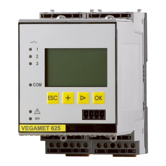
Signal conditioning and display instrument for level sensors
Hide thumbs
Also See for VEGAMET 625:
- Operating instructions manual (68 pages) ,
- Supplementary instructions manual (64 pages) ,
- Operating instructions manual (60 pages)

Subscribe to Our Youtube Channel
Related Manuals for Vega VEGAMET 625


Summary of Contents for Vega VEGAMET 625
- Page 1 Operating Instructions Signal conditioning and display instrument for level sensors VEGAMET 625 Double channel HART Document ID: 28970...
-
Page 2: Table Of Contents
Interface measurement with VEGAFLEX ................ 42 Pump control 1/2 (running time controlled) ..............43 Tendency recognition ..................... 45 Flow measurement ......................46 9 Maintenance and fault rectification Maintenance ........................49 Rectify faults ........................49 Instrument repair ......................51 VEGAMET 625 • Double channel HART... - Page 3 10.2 Disposal ......................... 52 11 Supplement 11.1 Technical data ........................ 53 11.2 Overview applications/functionality ................55 11.3 Dimensions ........................57 Supplementary documentation Information: Supplementary documents appropriate to the ordered version come with the delivery. You can find them listed in chapter "Product descrip- tion". Editing status: 2013-06-18 VEGAMET 625 • Double channel HART...
-
Page 4: About This Document
This arrow indicates a single action. Sequence of actions Numbers set in front indicate successive steps in a procedure. Battery disposal This symbol indicates special information about the disposal of bat- teries and accumulators. VEGAMET 625 • Double channel HART... -
Page 5: For Your Safety
During work on and with the device the required personal protective equipment must always be worn. Appropriate use VEGAMET 625 is a universal signal conditioning instrument and power supply unit for connection of two HART sensors. You can find detailed information on the application range in chapter "Product description". -
Page 6: Ce Conformity
That is why we have introduced an environment management system with the goal of continuously improving company environmental pro- tection. The environment management system is certified according to DIN EN ISO 14001. Please help us fulfill this obligation by observing the environmental instructions in this manual: • Chapter "Packaging, transport and storage" • Chapter "Disposal" VEGAMET 625 • Double channel HART... -
Page 7: Product Description
– Supplementary instructions manual 30768 "Modbus-TCP, VEGA ASCII protocol" (optional) – Ex-specific "Safety instructions" (with Ex versions) – if necessary, further certificates Constituent parts The VEGAMET 625 consists of the components: • VEGAMET 625 signal conditioning instrument with display and adjustment unit in the front • Terminal socket Ser. No. VEGAMET 12345678... -
Page 8: Principle Of Operation
On instruments with one of the optional interfaces (RS232/Ethernet), the measured values can be retrieved via modem or network and dis- played by means of a web browser, Visual VEGA or WEB-VV. It is also possible to send measured values and messages via e-mail. The use of VEGAMET 625 is particularly suitable for stocktaking, VMI (Vendor Managed Inventory) and remote enquiry. -
Page 9: Packaging, Transport And Storage
3 Product description Further instructions for setting up the web server and e-mail functions can be found in the online help of PACTware or the VEGAMET 625 DTMs as well as the operating instructions manual "RS232/Ethernet connection". Packaging, transport and storage Packaging Your instrument was protected by packaging during transport. Its capacity to handle normal loads during transport is assured by a test based on ISO 4180. -
Page 10: Mounting
If this rule is not heeded, there is a danger of coming into contact with the operating voltage or causing a short circuit. A VEGAMET 625 in Ex version is an auxiliary, intrinsically safe instru- ment and may not be installed in explosion-endangered areas. - Page 11 VEGA 10 o 11 o 12 o 12 o Fig. 2: Plug-in socket VEGAMET 625 Ex separating chamber Ex coding with Ex version Type coding for VEGAMET 624/625 Bridges for looping the operating voltage VEGAMET 625 • Double channel HART...
-
Page 12: Connecting To Power Supply
(low impedance). If potential equalisation currents are expected, the screen connection on the side of VEGAMET 625 must be made via a ceramic capacitor (e. g. 1 nF, 1500 V). The low frequency potential equalisation currents are thus suppressed, but the protective effect against high frequency interference signals remains. - Page 13 3. When using several sockets, loop the power supply by means of bridges 4. Connect power supply (switched off) to terminal 17 and 18 5. If necessary, connect relays or other outputs 6. Insert VEGAMET 625 into the plug-in socket and screw it down tightly Note: If the addressing of the sensors has not yet been carried out, only one sensor must be connected. Addressing (see chapter "Setup") of the...
-
Page 14: Wiring Plan
15 16 17 18 19 20 21 22 23 24 25 26 27 28 L1 N Fig. 3: Wiring plan VEGAMET 625 with two-wire sensors Internal operating relay 1 Internal operating relay 2 Internal operating relay 3 Internal current output 1... - Page 15 15 16 17 18 19 20 21 22 23 24 25 26 27 28 L1 N Fig. 4: Wiring plan VEGAMET 625 with four-wire sensors Internal operating relay 1 Internal operating relay 2 Internal operating relay 3 Internal current output 1...
-
Page 16: Setup With The Integrated Display And Adjustment Unit
Function The integrated display and adjustment unit is used for measured value display, adjustment and diagnosis of VEGAMET 625 as well as the connected sensors. The indication and adjustment are carried out via four keys and a clear, graphic-capable display with background lighting. -
Page 17: Setup Steps
(RS232/Ethernet) or the interface converter VEGACONNECT. Further instructions for setting up the web server and e-mail functions are stated in the online help of PACTware or the VEGAMET 625 DTMs as well as the supplementary instructions manual "RS232/Ethernet connection". - Page 18 Diagnosis Includes information to the device status, error mes- sages • Service Includes simulation, reset, PIN, selectable language, sensor address, … • Info: Shows serial number, software version, last change, instru- ment features, MAC addr., … VEGAMET 625 • Double channel HART...
- Page 19 [OK]. After the first setup, you can modify the inputs also under "Meas. loop - Input". Device settings - Device- You can assign an unambiguous name to VEGAMET 625 via the Device-TAG. This function is recommended when several instruments are implemented and a good documentation of larger systems is required.
- Page 20 ASCII protocol: Direct standard connection between signal con- ditioning instrument and PC for enquiry with terminal programs, e.g. Hyperterminal → Carry out your settings via the respective keys and save with [OK]. Further information is available in the supplementary VEGAMET 625 • Double channel HART...
- Page 21 DTM. Measurement loop - Input Because VEGAMET 625 has two inputs, the measurement loops must be assigned to the inputs. After the addresses of the HART sen- sors are assigned, a list of the existing sensors can be prepared and displayed via the sensor search.
- Page 22 0 and 999 seconds. Remember that the reaction time of the entire measurement will then be longer and the sensor will react to measured value changes with a delay. In general, a period of a few seconds is sufficient to smooth the measured value display. VEGAMET 625 • Double channel HART...
- Page 23 → Enter the requested parameters via the appropriate keys and save your settings with [OK]. Meas. loop - Outputs - Under "Outputs" you will find the relay/current outputs. With relay Relays outputs output, first of all the requested mode ("Overfill protection" or "Dry running protection") must be selected. VEGAMET 625 • Double channel HART...
- Page 24 The characteristics of the current outputs can be set to 0 … 20 mA, 4 … 20 mA or inverted. The reaction in case of failure can be also adapted to the requirements. The parameter to which they refer can also be selected. VEGAMET 625 • Double channel HART...
- Page 25 Note: Please note that connected system parts (valves, pumps, motors, control systems) are influenced by the simulation, thus unintentional plant operating conditions can occur. The simulation is terminated automatically after approxminately 10 minutes. VEGAMET 625 • Double channel HART...
- Page 26 In mode HART Multidrop, an address from 1 … 15 is assigned to the sensor. By doing so, the current is fix limited to 4 mA and the meas- ured value transmission is only made digitally. Each sensor connected to VEGAMET 625 must operate in mode HART multidrop and must be provided with different addresses in the range between 01 … 15. Via the menu item "Sensor address", it is possible to change the address of the connected sensor. For this purpose, enter the previous address of the sensor (factory setting 0) and in the next window the new address.
-
Page 27: Menu Schematic
Menu schematic Information: Depending on the instrument version and application, the highlighted menu windows are not always available. Measured value indication VEGAMET 625 • Double channel HART... - Page 28 6 Setup with the integrated display and adjustment unit Device settings Device settings - Input VEGAMET 625 • Double channel HART...
- Page 29 6 Setup with the integrated display and adjustment unit Measurement loops 1/2 - Input Meas. loop 1/2 - Change input Meas. loop 3 - Change input VEGAMET 625 • Double channel HART...
- Page 30 6 Setup with the integrated display and adjustment unit Meas. loop 1/2 - Parameter Meas. loop 3 - Parameter Meas. loop - Adjustment Meas. loop - Damping VEGAMET 625 • Double channel HART...
- Page 31 6 Setup with the integrated display and adjustment unit Meas. loop - Linearization curve Meas. loop - Scaling Meas. loop - Meas. loop TAG Meas. loop - Output - Relay VEGAMET 625 • Double channel HART...
- Page 32 6 Setup with the integrated display and adjustment unit Meas. loop - Output - Current outputs Display Diagnostics VEGAMET 625 • Double channel HART...
- Page 33 6 Setup with the integrated display and adjustment unit Service Service - Simulation Service - Sensor address Service - Data transmission (only with option RS232/Ethernet interface) VEGAMET 625 • Double channel HART...
- Page 34 6 Setup with the integrated display and adjustment unit Info VEGAMET 625 • Double channel HART...
-
Page 35: Setup With Pactware
To respond the instrument, the IP address or the Host name must be known. You can find this information under the menu item "Device settings". If you are modifying these specifications, the instrument must be restarted afterwards. Then the instruments can be reached from everywhere in the network via its IP address or the Host name. These specifications must be also entered in the DTM (see chapter "Parameter adjustment with PACTware"). VEGAMET 625 • Double channel HART... - Page 36 RS232 modem connection cable. If there is no RS232 interface available on the PC or if it is already occupied, you can also use a USB-RS232 adapter (e.g. article no. 2.26900). VEGAMET 625 • Double channel HART...
-
Page 37: Parameter Adjustment With Pactware
Collection. Furthermore, the DTMs can be integrated into other frame applications compliant with the FDT standard. Note: To ensure that all instrument functions are supported, you should always use the latest DTM Collection. Furthermore, not all described functions are included in older firmware versions. You can download VEGAMET 625 • Double channel HART... -
Page 38: Setup Web Server/E-Mail, Remote Enquiry
Setup and application examples of the web server, the e-mail func- tions and the visualisation WEB-VV are specified in the supplemen- tary instructions "RS232/Ethernet connection". The connection via Modbus-TCP or ASCII protocol is described in the supplementary instruction manual "Modbus-TCP, ASCII protocol". Both supplementary instruction manuals are included with every instrument with RS232 or Ethernet interface. VEGAMET 625 • Double channel HART... -
Page 39: Application Examples
2 (dry run protection). The max. volume should be at 90 % level, these are 9538 litres with a standard vessel (according to bearing chart). The min. level should be adjusted VEGAMET 625 • Double channel HART... -
Page 40: Weir Control Of A Water Power Station
(downstream water) is measured each with a VEGAWELL 72 HART. VEGAMET 625 generates the difference (h3) out of these two levels (measurement loop 3). If this difference is too high, a signal will be outputted by one of the integrated relays triggering the weir cleaning. Exemplary we assume a max. level of 2 m, the weir cleaning should be started at a difference of 20 cm. VEGAMET 625 • Double channel HART... - Page 41 - Measurement loop 1 - Input - Change input 1 - Sensor selection" to the menu item "Sensor list". Select the second sensor with address 02 – Measurement loop 3 (difference): This measurement loop calculates automatically without further settings the difference between upstream water and downstream water (measurement loop 1 minus measurement loop 2) VEGAMET 625 • Double channel HART...
-
Page 42: Interface Measurement With Vegaflex
Via the adjustment in VEGAMET 625 the level, interface and layer thickness of the upper medium can be calculated and displayed. -
Page 43: Pump Control 1/2 (Running Time Controlled)
8 Application examples instructions manual of VEGAFLEX. For this application, do not enter a dielectric figure directly on VEGAFLEX, because this value will be overwritten automatically by VEGAMET 625 • Adjustment – Each VEGAFLEX is shipped with default settings. The values of this adjustment are automatically tranferred to VEGAMET 625 during the setup of the interface measurement. - Page 44 • Input signal is higher than the upper switching point -> Relay with the shortest switch on period is switched on VEGAMET 625 • Double channel HART...
-
Page 45: Tendency Recognition
• Max. reaction time: Time after which a new measured value generation is carried out and the measured value change is recalculated • Hysteresis: is automatically always 10 % of the value of "Meas- ured value change larger than" VEGAMET 625 • Double channel HART... -
Page 46: Flow Measurement
Old average value = 62.5 %, new average value = 75 % Difference < 25 % -> Relay ON tm -> max. reaction time Flow measurement Functional principle For flow measurement in open flumes, a contraction or standardised flume must be used. Depending on the flow volume, this contraction generates a certain backwater. The flow can be determined from the height of this backwater. The flow volume is outputted by an appropri- ate number of pulses on the relay or current output. VEGAMET 625 • Double channel HART... - Page 47 Fig. 16: Adjustment of flow measurement with V-notch Linearization curve Select in the DTM window "Linearization" the option "Flow" and then the used flume (in the above example V-notch). Scaling Select in the DTM window "Scaling" under "Parameter" the option "Flow". Finally the allocation of a value must be carried out, i.e. the flow volume is assigned to the 0 and 100 % value. As the last step, select the requested meas. unit. For above example: 0 % = 0 and 100 % = 400, meas. unit m³/h. VEGAMET 625 • Double channel HART...
- Page 48 In mode "Sampling pulse" an additional pulse is outputted after a defined time. This means that a timer is started after each pulse after which another pulse is outputted. This applies only if already a pulse was outputted after exceeding the flow volume. Due to sludge at the bottom of the flume, it can happen that the min. adjustment originally carried out can no longer be reached. Therefore small quantities will continuously enter the flow volume detection despite the "empty" flume. The option "Min. flow volume suppression" offers the possibility to suppress measured flow volumes below a certain percentage value for the flow volume detection. VEGAMET 625 • Double channel HART...
-
Page 49: Maintenance And Fault Rectification
24 hour service hotline Should these measures not be successful, please call in urgent cases the VEGA service hotline under the phone no. +49 1805 858550. The hotline is available to you 7 days a week round-the-clock. Since we offer this service world-wide, the support is only available in the English language. - Page 50 ROM CRC error – Switch the instrument off and on – Carry out a reset – Send instrument for repair E036 Instrument software – Wait until software update is finished not executable (dur- – Carry out another software update ing software update or after failed update) VEGAMET 625 • Double channel HART...
-
Page 51: Instrument Repair
If a repair is necessary, please proceed as follows: You can download a return form (23 KB) from our Internet homepage www.vega.com under: "Downloads - Forms and certificates - Repair form". By doing this you help us carry out the repair quickly and without hav- ing to call back for needed information. -
Page 52: Dismounting
WEEE directive. Correct disposal avoids negative effects on humans and the environ- ment and ensures recycling of useful raw materials. Materials: see chapter "Technical data" If you have no way to dispose of the old instrument properly, please contact us concerning return and disposal. VEGAMET 625 • Double channel HART... -
Page 53: Supplement
10 mV DC, max. 250 V AC/DC Switching current min. 10 µA DC, max. 3 A AC, 1 A DC Breaking capacity min. 50 mW, max. 750 VA, max. 40 W DC (with U less than 40 V) VEGAMET 625 • Double channel HART... - Page 54 1 x LED red Ʋ Status operating relay 1/2/3 3 x LED yellow Ʋ Status interface 1 x LED green Adjustment Adjustment elements 4 x keys for menu adjustment PC adjustment PACTware with respective DTM VEGAMET 625 • Double channel HART...
-
Page 55: Overview Applications/Functionality
Approvals Instruments with approvals can have different technical data depending on the version. For that reason the associated approval documents of these instruments have to be carefully noted. They are part of the delivery or can be downloaded under www.vega.com via "VEGA Tools" and "serial number search" as well as via "Downloads" and "Approvals". 11.2 Overview applications/functionality The following charts provide an overview of the standard applications and functions of signal condi- tioning instruments VEGAMET 391/624/625 and VEGASCAN 693. - Page 56 Parameter adjustment of PC/DCS output • • • • • Web-VV settings • • • • • Device trend • • • • • Configure transmission of measured values via e-mail • • • • • Configure transmission of measured values via SMS • • • • • VEGAMET 625 • Double channel HART...
-
Page 57: Dimensions
11 Supplement 11.3 Dimensions Ser. No. 12345678 9 10 11 12 13 14 15 16 23 24 25 26 27 28 17 18 20 21 22 130 mm (5.12") 72 mm (2.84") VEGAMET 625 • Double channel HART... - Page 58 Les lignes de produits VEGA sont globalement protégées par des droits de propriété intellec- tuelle. Pour plus d'informations, on pourra se référer au site www.vega.com. VEGA lineas de productos están protegidas por los derechos en el campo de la propiedad indus- trial. Para mayor información revise la pagina web www.vega.com.
- Page 59 – Causes 49 Network 17 – Fault message 25, 50 – Rectification 49 Online help 27, 38 Flow measurement 24, 46 Overfill protection 6, 24, 39 Fluctuating product surface 22 Functional principle 8 PACTware 8, 17, 24 VEGAMET 625 • Double channel HART...
- Page 60 Software update 37 Spherical tank 23 Subnet mask 19 Switching window 24 Tank calculation 38 Tendency 24 Tendency recognition 45 Time setting 20 TÜV (Technical Control Board) 6 Type plate 7 – USB - RS232 adapter 36 Visualization 35 VEGAMET 625 • Double channel HART...
- Page 61 Notes VEGAMET 625 • Double channel HART...
- Page 62 Notes VEGAMET 625 • Double channel HART...
- Page 63 Notes VEGAMET 625 • Double channel HART...
- Page 64 Subject to change without prior notice © VEGA Grieshaber KG, Schiltach/Germany 2013 VEGA Grieshaber KG Phone +49 7836 50-0 Am Hohenstein 113...
Need help?
Do you have a question about the VEGAMET 625 and is the answer not in the manual?
Questions and answers