Table of Contents
Advertisement
Advertisement
Table of Contents

Related Manuals for Cervis Wireless SmaRT BU- H1R Series


Summary of Contents for Cervis Wireless SmaRT BU- H1R Series
- Page 1 ™ BU-xH1R 900 MHz and 2.4 GHz Base Units Manual U099.0.2 ©2020 Cervis, Inc.
- Page 2 BU-xH1R Base Unit Family This document is the property of Cervis, Inc. and cannot be copied, modified, e-mailed, or reproduced without the express prior written consent of Cervis, Inc. Cervis, Inc. reserves the right to change this manual or edit, delete, or modify any information without prior notification.
-
Page 3: Table Of Contents
Table of Contents List of Figures ..........................i List of Tables ..........................i Cervis, Inc. Safety Precautions ....................ii 1.0 SmaRT BU-xH1R Base Unit and Handheld Remote Control ........... 1 2.0 SmaRT BU-xH1R Base Unit ....................2 2.1 Base Unit Installation ....................... 3 2.2 SmaRT BU-xH1R5 P1 Connector Wiring ................ -
Page 4: Cervis, Inc. Safety Precautions
BU-xH1R Base Unit Family Cervis, Inc. Safety Precautions ✓ Read and follow all instructions. ✓ Failure to abide by Safety Precautions may cause equipment failure, loss of authority to operate the equipment, and personal injury. ✓ Use and maintain proper wiring. Follow equipment manufacturer instructions. -
Page 5: Smart Bu-Xh1R Base Unit And Handheld Remote Control
900MHz & 2.4GHz Manual SmaRT BU-xH1R Base Unit and Handheld Remote Control Note: The “x” in BU-xH1R represents both 900 MHz (9) and 2.4 GHz (2) base units. A standard SmaRT BU-xH1R remote control system consists of a SmaRT BU-xH1R base unit and a SmaRT handheld remote control unit. -
Page 6: Smart Bu-Xh1R Base Unit
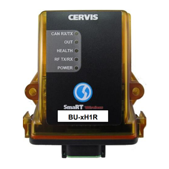
BU-xH1R Base Unit Family 2.0 SmaRT BU-xH1R Base Unit The SmaRT BU-2H1R5 and BU-9H1R5 base units feature one Form C relay output and five Form A relay outputs. CAN bus capable base units—BU-2H1R3 and BU-9H1R3—have one Form C and three Form A relay outputs. The BU-xH1R family of base units accepts a broad range of operating input power with model-dependent operating voltages of 7–32 VDC, 7–28 VAC, and 100–240 VAC. -
Page 7: Base Unit Installation
Make sure the machine that the base unit will be attached to is disabled during installation. Use the configuration diagrams supplied by Cervis, Inc. to guide you in mounting the base unit and connecting your wiring harness cables. Mounting of the base unit is left much to your discretion with the following guidelines: •... -
Page 8: Figure 3. Mounting Holes And Cable Connector P1
BU-xH1R Base Unit Family 102 mm (4") center-to-center Mount with Connectors 7.4mm (0.29”)dia. Facing Downward BU-xH1R BU-xH1R 118mm (4.7") 2.4 GHz 146.05 mm (5.75") 36mm (1.4") 900 MHz 196 mm (7.7") Figure 3. Mounting Holes and Cable Connector P1 U099.0.2... -
Page 9: Smart Bu-Xh1R5 P1 Connector Wiring
Form A Relay Hi VAC Neutral/Hi –VDC Form A Relay Lo VAC Neutral/Lo –VDC Form A Relay +VDC or VAC Line Form A Relay Form C Relay NC KCOM Control Voltage Form C Relay Common Form C Relay NO ©2020 Cervis, Inc... -
Page 10: Smart Bu-Xh1R3 P1 Connector Wiring
BU-xH1R Base Unit Family 2.3 SmaRT BU-xH1R3 P1 Connector Wiring Figure 5. BU-xH1R3 P1 Connector CAN Wiring Table 2. SmaRT BU-xH1R3 P1 Connector Pin Assignments Name Description Name Description Form A Relay CAMH CANH Hi VAC Neutral/Hi –VDC Form A Relay Lo VAC Neutral/Lo –VDC CANL CANL... -
Page 11: Base Unit Troubleshooting
Power LED not Is input power Check input power polarity. active present? Power LED Red or Indicates an internal Contact Cervis, Inc. service department. Green component failure. ✓ Is the system using CAN? ✓ Check for obstructions preventing line-of-sight CAN RX/TX not transmission. -
Page 12: Specifications
BU-xH1R Base Unit Family 3.0 Specifications Table 4. SmaRT BU-xH1R Base Unit Specifications Item Description Power See Appendix A –25° C to 60° C (–4° F to 131° F) Operating Temp Environment –40° C to 85° C (–40° F to 185° F) Storage Temp Humidity 0 to 100%... -
Page 13: Appendix A: Bu-Xh1R Hardware Options
External BU-2H1R5-EXT-LVA 2.4 GHz/100 mW 6/Form C, 5 Form A 7–28 VAC External BU-2H1R3-EXT-LVA-CAN 2.4 GHz/100 mW 4/Form C, 3 Form A 7–28 VAC External BU-2H1R5-EXT-LVA-NOS 2.4 GHz/100 mW 6/Form C, 5 Form A 7–28 VAC External ©2020 Cervis, Inc... -
Page 14: Appendix B: Bu-Xh1R Wiring Harness
BU-xH1R Base Unit Family Frequency/ # of Channels Serial Model Name Input Power Antenna RF Power /Relay Types Port Suppression BU-2H1R3-EXT-LVA-NOS-CAN 2.4 GHz/100 mW 4/Form C, 3 Form A 7–28 VAC External BU-2H1R5-EXT-HVU 2.4 GHz/100 mW 6/Form C, 5 Form A 100–240 VAC External BU-2H1R3-EXT-HVU-CAN... -
Page 15: Appendix D: Agency Identification Label Location
Note: Individual agency labels may differ, but SmaRT base unit and handheld remote models use the illustrated label positions for all agency labels. It is identical for both internal antenna and external antenna base units. Figure 7. Agency Identification Label Locations ©2020 Cervis, Inc... - Page 16 BU-xH1R Base Unit Family www.cervisinc.com Visit our Web site at: ©2020 Cervis, Inc. All rights reserved. Content is subject to change without notice. U099.0.2...
Need help?
Do you have a question about the Wireless SmaRT BU- H1R Series and is the answer not in the manual?
Questions and answers