
Related Manuals for Cervis SmaRT 902


Summary of Contents for Cervis SmaRT 902
- Page 1 SmaRT 902 Remote Control System Manual U007.0-SmaRT902_system-R ©2007 Cervis, Inc.
-
Page 2: Fcc Statements
This document is the property of Cervis, Inc. and cannot be copied, modified, or reproduced without the express prior written consent of Cervis, Inc. Cervis, Inc. reserves the right to change this manual or edit, delete, or modify any information without prior notification. -
Page 3: Table Of Contents
User Manual Contents FCC Statements ..........................i 1.0 SmaRT 902 Remote Control System.................. 1 1.1 Features ..........................1 1.2 PT0-902 Handheld Remote ....................2 1.3 BU-902F Base Unit......................2 1.4 Communication Configuration Options ................. 3 1.4.1 Associate Handheld to Base Unit Procedure............... 3 1.4.2 Disassociate Handheld to Base Unit Procedure ............ - Page 4 SmaRT 902 Remote Control System Notes: U007.0-SmaRT902_system-R...
-
Page 5: Smart 902 Remote Control System
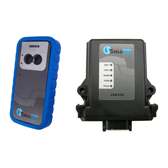
Product Name 1.0 SmaRT 902 Remote Control System The standard SmaRT 902 Remote Control System consists of a 2-button PTO-902 wireless handheld transmitter, a BU-902F base unit, and the wiring harness that is used to connect the base unit to the controlled apparatus. A single base unit is capable of communicating with up to eight PTO-902 Handheld units. -
Page 6: Pt0-902 Handheld Remote
SmaRT 902 Remote Control System 1.2 PT0-902 Handheld Remote The SmaRT PTO-902 Handheld Remote features a 300’ handheld-to-base unit com- munication range providing two function press-to-operate (PTO) control. Using direct sequence spread spectrum (DSSS) wireless technology at 900MHz, the handheld unit provides a robust link with a base unit in congested radio environments. -
Page 7: Communication Configuration Options
Figure 4. BU-902F LEDs 1.4 Communication Configuration Options A standard SmaRT 902 System comes with one PTO-902 Handheld Remote and one BU-902F Base Unit, but each base unit can establish communication with up to eight PTO-902 Handheld Remotes. Each handheld must first establish a communications link with the base unit before the base unit can recognize the handheld unit. -
Page 8: Disassociate Handheld To Base Unit Procedure
TX lights steady green and remains so until the button is released. 8. Release the Associate button. The RX LED extinguishes, the TX LED flashes green for a brief time, and then it too extinguishes. The SmaRT 902 System is ready for use with that particular handheld remote. ASSOCIATE DISASSOCIATE... - Page 9 The SmaRT BU-902F Base Unit will not communicate with any handheld remote units. A handheld remote must use the Association Procedure to re-establish a communica- tion link with the base unit. ©2007 Cervis, Inc.
-
Page 10: Handheld Battery Installation Or Change
SmaRT 902 Remote Control System 2.0 Handheld Battery Installation or Change The SmaRT handheld unit is powered by three size AAA batteries. When installing bat- teries, be sure to observe proper polarity as marked on the inside of the compartment to avoid damaging the unit. -
Page 11: Base Unit Installation
Make sure the machine on which the base unit is to be attached is disabled during installation. Use the configuration diagrams supplied by Cervis to guide you in mounting the base unit and connecting your wiring harness. Mounting of the base unit is left much to your discretion with the following guidelines: •... -
Page 12: Using The Smart Pto-902 Handheld Remote
SmaRT 902 Remote Control System Using the SmaRT PTO-902 Handheld Remote The front panel of the SmaRT PTO-902 Handheld Remote has two (2) push-to-operate buttons and three (3) diagnostic LEDs. Each of the two buttons have dual functions as described in Figure 9. -
Page 13: Wiring Harness
User Manual Wiring Harness ©2007 Cervis, Inc. -
Page 14: Specifications
SmaRT 902 Remote Control System 6.0 Specifications 6.1 Handheld Table 1 - Handheld Specifications Item Description Power +3.6V to +4.5V Batteries Three (3) AAA Auto-shutdown 5 Sec. of button inactivity Environment -20°C to 55°C Operating (-4°F to 131°F) -40°C to 55°C Storage (-40°F to 131°F) -
Page 15: Base Unit
(5.24” x 4.69” x 1.42”) Durability High Impact Polymer Indicators Power Yellow Red/green Fault TX/RX Green Receive Transmit Health Green Pulse/Sec. LED1 Green Output 1 Active LED2 Green Output 2 Active Outputs FET XVDC 8A max. high-side switching ©2007 Cervis, Inc. - Page 17 Cervis, Inc. www.cervisinc.com Visit our Web site at: The SmaRT Remote Control System is manufactured and distributed by Cervis, Inc. © 2007 Cervis, Inc. All rights reserved. Content is subject to change without notice. ©2007 Cervis, Inc. U007.0-SmaRT902_system-R...
Need help?
Do you have a question about the SmaRT 902 and is the answer not in the manual?
Questions and answers