
Related Manuals for StepperOnline DM556T


Summary of Contents for StepperOnline DM556T
- Page 1 DM556T Digital Stepper Drive User Manual User Manual DM556T 2-Phase Digital Stepper Drive Record of Revisions Manual Revision Date Description of Release V1.0 Oct. 2022 Initial Release...
-
Page 2: Table Of Contents
DM556T Digital Stepper Drive User Manual Table of Contents 1. Features ................................... 1 2. Specifications .................................. 1 2.1 Electrical Specifications ............................1 2.2 Environment ................................1 2.3 Mechanical Specifications ............................. 1 2.4 Elimination of Heat ..............................2 3. Connection Pin Assignments and LED Indication ..................... 2 3.1 Control Connector ..............................2... -
Page 3: Features
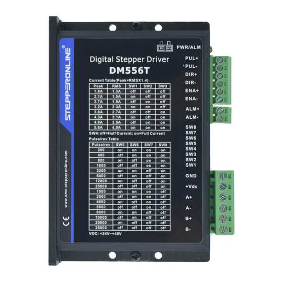
DM556T Digital Stepper Drive User Manual 1. Features Step & direction (PUL/DIR) control Input voltage 20~50VDC 200 KHz max pulse input frequency 16 microstep resolutions of 200-51,200 via DIP switches 8 output current settings of 1.8-5.6A via DIP Switches ... -
Page 4: Elimination Of Heat
Side mounting recommended for better heat dissipation 2.4 Elimination of Heat DM556T reliable working temperature should be < 40℃ (109°F) It is recommended to use automatic idle-current mode to reduce motor heating. That means set the SW4 ... -
Page 5: Fault Output Connector
3.4 LED Light Indication There are two LED lights for DM556T. The GREEN one is the power indicator which will be always on generally. The RED one is a protection indicator which will flash 1-2 times in a 3-second period, when protection enabled for a DM556T. -
Page 6: Motor Connection
Figure 7 4-lead Motor Connections 6. Power Supply Selection The DM556T can power medium and large size stepping motors (frame size from NEMA 23 to 24). To get good driving performances, it is important to select supply voltage and output current properly. Generally speaking, supply voltage determines the high speed performance of the motor, while output current determines the output torque of the driven motor (particularly at lower speed). -
Page 7: Selecting Supply Voltage
7. DIP Switch Configurations The DM556T has an 8-bit DIP switch and a 1-bit DIP switch. The first 8-bit is used to configure settings of micro step resolution, output current, motor standstill current as shown below. -
Page 8: Dynamic Current Configurations
If only one power supply serves multiple DM556T drives, separately connecting the drives to the power supply is recommended instead of daisy-chaining. -
Page 9: Sequence Chart Of Control Signals
DM556T Digital Stepper Drive User Manual Figure 8 Typical Connections 10. Sequence Chart of Control Signals In order to avoid some fault operations and deviations, PUL, DIR and ENA should abide by some rules, shown as following diagram: Figure 9 Sequence charts of control signals Remark: t1: ENA must be ahead of DIR by at least 200ms. -
Page 10: Troubleshooting
DM556T Digital Stepper Drive User Manual Time(s) of Priority Sequence wave of red LED Description Blink Over-current protection activated when peak current exceeds the limit. Over-voltage protection activated when drive working voltage is greater than 60VDC Reserved. When above protections are active, the motor shaft will be free or the red LED blinks. Reset the drive by repowering it to make it function properly after removing above problems.
Need help?
Do you have a question about the DM556T and is the answer not in the manual?
Questions and answers