Table of Contents
Advertisement
Quick Links
Advertisement
Table of Contents

Related Manuals for FETtec FC G4


Summary of Contents for FETtec FC G4
- Page 1 FETtec FC G4 Manual Page 1...
-
Page 2: Table Of Contents
Table of Contents Introduction.............................3 Features............................3 Safety warning..........................4 Recommended steps for installation of the FETtec FC G4............4 Connection Diagram........................5 Connection Layout top.......................5 Connection Layout bottom......................6 ESC connection diagram........................8 ESC connection via 8 pin connector ..................8 Single ESC connection diagram....................9 Receiver connection diagram.......................10 TBS Crossfire...........................10... -
Page 3: Introduction
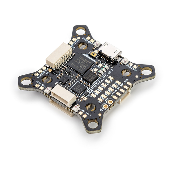
Introduction Thank you for purchasing the FETtec FC G4. Features Latest STM32G4 Processor • ◦ 170Mhz + Math accelerator ◦ MPU6000 Supply voltage 6-27V (2S-6S Lipo) • 2x dedicated onboard BEC (max. 600mA each) • ◦ 5V BEC for RX ◦... -
Page 4: Safety Warning
Install the FC in your copter (see Connection diagrams for correct wiring and installation) • Make sure everything is connected properly and check without propellers • Connect to KISS GUI to proceed with final configuration of the FETtec FC G4 (FC • configuration) Page 4... -
Page 5: Connection Diagram
Connection Diagram Connection Layout top The 8 pin connector combines all necessary connections for analog or digital VTX and camera. It includes: Real Pit VCC (Lipo+) • GND for cam and VTX • Video in: Analog video signal from cam •... -
Page 6: Connection Layout Bottom
Connection Layout bottom 8 pin ESC connector 1: VCC: Battery voltage out to supply FC power • • TLM/Onewire: ESC Telemetry signal to FC or Onewire signal pin (depending on • configuration) ESC signal 1-4: ESC signal output for each ESC •... - Page 7 Receiver connector: • • TLM: Telemetry signal to receiver (see page 10 receiver connection diagram for further • information) Signal: Receiver signal to FC (see page 10 receiver connection diagram for further • information) 6 pin connector (SER1): RX1: function configurable in GUI •...
-
Page 8: Esc Connection Diagram
ESC connection via 8 pin connector For easy ESC connection via 8 pin cable FETtec FC G4 to FETtec 4in1 ESC 45A (same for FETtec 4in1 ESC 35A), cable included with FETtec ESCs. Any other ESC is usable (please make sure the signal pinout is correct, otherwise change... -
Page 9: Single Esc Connection Diagram
Single ESC connection diagram The FETtec FC G4 provides 4 ESC signal pads for solder connection of single ESCs Page 9... -
Page 10: Receiver Connection Diagram
Receiver connection diagram Receivers can be connected via receiver connector (on bottom side of FC) or receiver solder pads (on top side of FC) TBS Crossfire SBUS receiver / FrSky R-XSR Page 10... -
Page 11: Analog Fpv Connection Diagram
Analog FPV connection diagram VTX and cam can be connected via FPV connector (on top side of FC) or FPV solder pads (on top side of FC) Note: RX and TX connection is only used for cameras which support serial connection Page 11... -
Page 12: Digital Fpv Connection Diagram
Digital FPV connection diagram Caddx Vista FPV system Fatshark Shark Byte system Page 12... -
Page 13: Fc Configuration
Download KISS GUI: https://github.com/flyduino/kissfc-chrome-gui/releases After installing the KISS GUI connect the FETtec FC G4 via USB. Open the KISS GUI and select the serial port on which the FC shows up and press connect. Activate the FETtec FC G4 in the KISS GUI by pressing activate on the following prompt Now you can set up the FC according to your wishes. -
Page 14: Fc Firmware Update
FC firmware update For Firmware updates download the FETtec Configurator available here: https://github.com/FETtec/Firmware/releases After installing the FETtec Configurator open it and select the serial port the FC shows up and press connect. choose USB and select the correct COM Port and press connect. -
Page 15: Osd Firmware
OSD Firmware Please update the FETtec OSD Board before your first flight ! To update the FETtec OSD connect to FETtec Configurator and flash via FC passthrough latest firmware. Settings All settings can be set up directly in the OSD... - Page 16 In the menu: OSD settings: Page 16...
-
Page 17: Issues In The Picture
Issues in the picture 1. OSD SYNC → AUTO SYNC 2. in case of unsharp lines play with LEFT/WITH values try to avoid WITH values above 400 3. make a PAL/NTSC layout reset Move elements in the OSD menu Choose LAYOUT → SET POSITIONS in the SETTINGS. Now the elements are movable along the grid. -
Page 18: Dimensions
Dimensions Maximum outside dimensions: 37,2 x 37,2mm, without outside tips 30 x 30mm Mounting hole arrangement: 20 x 20mm with M2 mounting hole (expandable to M3) • 30 x 30mm with M3 mounting hole • 30 x 30mm mounting hole tips are removable to reduce overall FC size •...
Need help?
Do you have a question about the FC G4 and is the answer not in the manual?
Questions and answers