Table of Contents
Advertisement
Quick Links
Advertisement
Table of Contents

Related Manuals for FETtec FC G4-N


Summary of Contents for FETtec FC G4-N
- Page 1 FETtec FC G4 - N Manual Page 1...
-
Page 2: Table Of Contents
Introduction ..........................3 Features ............................3 Safety warning ..........................4 Recommended steps for installation of the FETtec FC G4 - N ............ 4 Connection Diagram ........................5 Connection Layout top ......................5 Connection Layout bottom ......................6 ESC connection diagram ......................8 ESC connection via 8 pin connector .................. -
Page 3: Introduction
Introduction Thank you for purchasing the FETtec FC G4 - N. Features • Latest STM32G4 Processor ◦ 170Mhz + Math accelerator ◦ MPU6000 • Supply voltage 6-27V (2S-6S Lipo) • 2x dedicated onboard BEC (max. 600mA each) ◦ 5V BEC for RX ◦... -
Page 4: Safety Warning
Install the FC in your copter (see Connection diagrams for correct wiring and installation) • Make sure everything is connected properly and check without propellers • Connect to KISS GUI to proceed with final configuration of the FETtec FC G4 - N (FC configuration) Page 4... -
Page 5: Connection Diagram
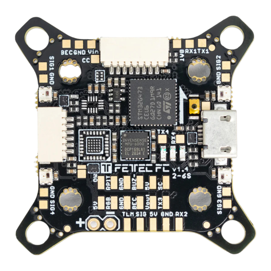
Connection Diagram Connection Layout top The 8 pin connector combines all necessary connections for analog or digital VTX and camera. It includes: • Real Pit VCC (Lipo+) • GND for cam and VTX • Video in: Analog video signal from cam •... -
Page 6: Connection Layout Bottom
Connection Layout bottom 8 pin ESC connector 1: • VCC: Battery voltage out to supply FC power • • TLM/Onewire: ESC Telemetry signal to FC or Onewire signal pin (depending on configuration) • ESC signal 1-4: ESC signal output for each ESC 8 pin ESC connector 2: •... - Page 7 Receiver connector: • • • TLM: Telemetry signal to receiver (see page 10 receiver connection diagram for further information) • Signal: Receiver signal to FC (see page 10 receiver connection diagram for further information) 6 pin connector (SER1): • RX1: function configurable in GUI •...
-
Page 8: Esc Connection Diagram
ESC connection via 8 pin connector For easy ESC connection via 8 pin cable FETtec FC G4 - N to FETtec 4in1 ESC 45A (same for FETtec 4in1 ESC 35A), cable included with FETtec ESCs. Any other ESC is usable (please make sure the signal pinout is correct, otherwise change... -
Page 9: Single Esc Connection Diagram
Single ESC connection diagram The FETtec FC G4 - N provides 4 ESC signal pads for solder connection of single ESCs Page 9... -
Page 10: Receiver Connection Diagram
Receiver connection diagram Receivers can be connected via receiver connector (on bottom side of FC) or receiver solder pads (on top side of FC) TBS Crossfire SBUS receiver / FrSky R-XSR Page 10... -
Page 11: Analog Fpv Connection Diagram
Analog FPV connection diagram VTX and cam can be connected via FPV connector (on top side of FC) or FPV solder pads (on top side of FC) Notes: RX and TX connection is only used for cameras which support serial connection. A unit's transmit signal (TX) must match the corresponding receiver (RX) at the other end. -
Page 12: Digital Fpv Connection Diagram
Digital FPV connection diagram Choose MSP Port on serial 3 in the FETtec ALPHA Configurator → Settings → FC setup → Serial or KISS GUI Caddx Vista FPV system Page 12... -
Page 13: Fatshark Shark Byte System
Fatshark Shark Byte system Caddx Walksnail Page 13... -
Page 14: Fc Configuration
KISS FC firmware Download KISS GUI: https://github.com/flyduino/kissfc-chrome-gui/releases After installing the KISS GUI connect the FETtec FC G4 - N via USB. Open the KISS GUI and select the serial port on which the FC shows up and press connect. Activate the FETtec FC G4 - N in the KISS GUI by pressing activate on the following prompt Now you can set up the FC according to your wishes. -
Page 15: Fc Firmware Update
FC firmware update 1. Open FETtec Toolset https://gui.fettec.net The FETtec ESC Configurator is also available as download version here: https://github.com/FETtec/ESC-Configurator 2. Open the FETtec ESC Configurator 3. Connect the FETtec FC via USB 4. choose USB and select the correct COM Port and press connect. -
Page 16: Fettec Alpha Fc Firmware
FETtec Alpha FC firmware The FETtec FC G4-N is able to use FETtec Alpha FC firmware. For install: 1. Open FETtec Toolset https://gui.fettec.net and choose ALPHA Configurator. 2. Connect the FETtec FC via USB. 3. Open the ALPHA Configurator and select open port. Choose the serial port on which the FC shows up and press connect. - Page 17 5. “Select new firmware to flash”. We always recommend flashing the latest available firmware. 6. Confirm to flash FETtec ALPHA firmware by pressing “OK” Page 17...
- Page 18 7. FC firmware update is done! The FC needs a restart after that, therefore the com port is requested to be selected and connected again Now you can customize everything in the GUI according to your wishes. Please connect everything like described in the manual of the FC. A unit's transmit signal (TX) must match the corresponding receiver (RX) at the other end.
-
Page 19: Get Back To Kiss
Get back to KISS If the FETtec Alpha FC firmware is flashed on your FC and you want to get back to KISS firmware, follow these steps: 1. Open FETtec Toolset https://gui.fettec.net/ 2. Connect the FETtec FC via USB. 3. Press the reset button once 4. - Page 20 7. Flashing to KISS FC firmware done. Page 20...
-
Page 21: Fc Firmware Update
FC firmware update For firmware updates it is the same procedure as flashing the FETtec Alpha FC firmware. Connect FC via open port and choose “Firmware”. Now you can flash the latest firmware update via “Select new firmware to flash” or choose “Flash local file”. -
Page 22: Settings
Settings You can set up the FC according to your wishes in the ALPHA Configurator. All functions are explained in the respective category. For more information and help use the FETtec Alpha FC firmware manual available at www.fettec.net/download Page 22... -
Page 23: Display Connection
Display connection I2C O-LED to FETtec FC G4-N I2C O-LED display can be used to show the OSD menu and telemetry in order to be able to set up settings without computer or FPV goggles (FPV OSD). The I2C connection will block serial 3 which is mostly used for digital OSD or analog VTX control (VCS). -
Page 24: Activation In Fettec Alpha Fc Firmware
Activation in FETtec Alpha FC firmware Page 24... -
Page 25: Dimensions
Dimensions Maximum outside dimensions: 37,2 x 37,2mm, without outside tips 30 x 30mm Mounting hole arrangement: • 20 x 20mm with M2 mounting hole (expandable to M3) • 30 x 30mm with M3 mounting hole • 30 x 30mm mounting hole tips are removable to reduce overall FC size Overall height: 7,9mm Highest part on each PCB side: 3,2mm Weight: 5,37g...
Need help?
Do you have a question about the FC G4-N and is the answer not in the manual?
Questions and answers