
Related Manuals for FETtec ESC 45A


Summary of Contents for FETtec ESC 45A
- Page 1 4in1 ESC 45A Manual You can find this manual online at www.fettec.net/downloads Page 1...
- Page 2 Table of Contents Introduction....................................3 Features........................................3 Safety warning..................................3 Connection Diagram................................4 Top/Bottom Layout.....................................4 Dimension (in mm)....................................4 Basic Setup....................................5 4S..........................................5 6S..........................................5 FETtec FC.........................................5 Betaflight.........................................6 Connection.......................................6 Configuration....................................6 FETtec Configurator................................7 Settings........................................7 Page 2...
- Page 3 Introduction Thank you for purchasing the FETtec ESC. This is a high-quality sensor-less brush-less electronic 4 in 1 speed control. Features Active current limiting @ 45A • Input voltage: 3S-6S • High quality 40V MOSFETs • STM32G071 @ 64MHz •...
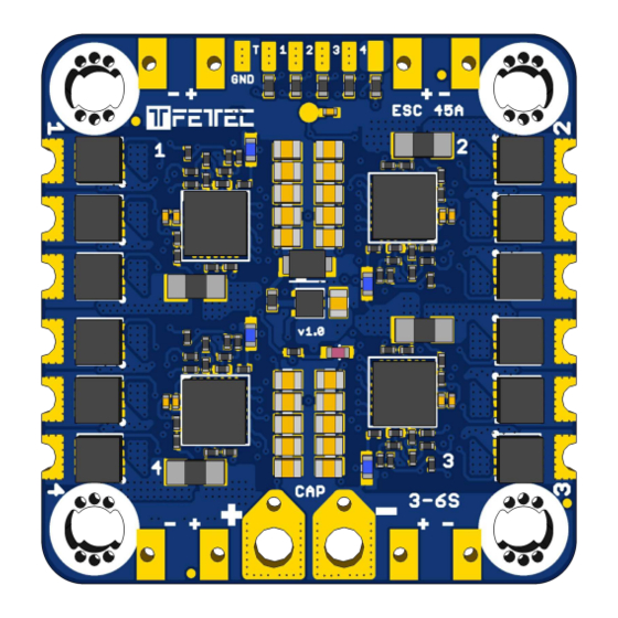
- Page 4 Connection Diagram Top/Bottom Layout S1 – S4 – Motor Signal 1-4 TLM – Telemetry (Serial) GND – Reference Signal Ground Dimension (in mm) The ESC comes with a 30,5x30,5mm mounting hole layout designed for M3 and M4 screws. Original is for M3 while you can use a screw driver and force it into M4 by rotating it inside the hole carefully.
- Page 5 ESC. Minimum 470uF ESR < 1ohm We recommend to use the provided 477CKE050M capacitor. FETtec FC Use the 8pin cable which comes with the ESC to connect it to the FETtec FC Page 5...
- Page 6 Betaflight Connection Signal 1 – 4 have to be connected to the corresponding FC Motor outputs. The TLM wire has to be connected to an available serial TX pin. Configuration In order to utilize ESC provided current and voltage sensor the following settings need to be applied to betaflight.
- Page 7 Please update your ESC periodically with the current Firmware version. The ESC configuration tool is available at https://github.com/FETtec/ESC-Configurator The ESC firmware is available for download at https://github.com/FETtec/ESC-Firmware FC passthrough is available for the following platforms: KISS FC – Firmware 1.3-RC36j (or higher) •...
- Page 8 The Setting page allows to adjust all available ESC parameter - Reverse rotation direction - Slow start - 3D mode - PWM min & max signal - ESC Beep enabled - Current calibration - Individual ESC ID (for use on onewire protocol) In Telemetry page you can spin the motors, view and debug the Motor telemetry.
Need help?
Do you have a question about the ESC 45A and is the answer not in the manual?
Questions and answers