Table of Contents
Advertisement
Quick Links
Advertisement
Table of Contents

Related Manuals for FETtec AIO 35A


Summary of Contents for FETtec AIO 35A
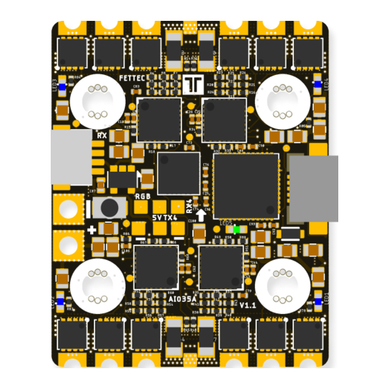
- Page 1 FETtec AIO 35A Manual Page 1...
-
Page 2: Table Of Contents
Table of Contents Introduction.............................3 Features............................3 Safety warning..........................5 Recommended steps for installation of the FETtec AIO 35A............5 Connection Diagram........................6 Connection Layout top.......................6 Connection Layout bottom......................7 Firmware update and settings......................8 FC Firmware update........................8 ESC Firmware update........................9 OSD Firmware update......................10 OSD Settings..........................11 Issues with the OSD.........................12 Move elements in the OSD menu....................12... -
Page 3: Introduction
Introduction Thank you for purchasing the FETtec AIO 35A. Features Latest STM32G4 Processor • ◦ 170Mhz + Math accelerator ◦ MPU6000 Supply voltage 12-25V (3S-6S Lipo voltage) • 2x dedicated onboard 5V BEC for VTX (max. 600mA each) • ◦ 5V BEC for RX ◦... - Page 4 • up to 128 kHz Motor PWM • Full sine wave control • Automatic input signal detection • ◦ PWM, Oneshot125, Oneshot42, Dshot150/300/600/1200/2400, FETtec Onewire FETtec ESC firmware • OSD: Onboard OSD • ◦ Graphic OSD (STM32) ◦ Full KISS Tuning ◦...
-
Page 5: Safety Warning
Install the AIO in your copter (see Connection diagrams for correct wiring and installation) • Make sure everything is connected properly and check without propellers • Connect to KISS GUI to proceed with final configuration of the FETtec AIO 35A (FC • configuration) Page 5... -
Page 6: Connection Diagram
Connection Diagram Connection Layout top Receiver connector: • • TLM: Telemetry signal to receiver • SIG.: Receiver signal to FC • Acronym explanation: Motor 1 - 4: pads for motor connection • GND: Reference Signal Ground • 3-6S - / +: Battery input voltage (12V-27V) •... -
Page 7: Connection Layout Bottom
Connection Layout bottom The 8 pin connector combines all necessary connections for analog or digital VTX and camera. It includes: VCC (Lipo+) • GND for cam and VTX • Video in: Analog video signal from cam • Video out: Analog video to VTX •... -
Page 8: Firmware Update And Settings
Firmware update and settings The FETtec AIO 35A works with KISS/FETtec FC firmware version 1.3RC47i or later ! The FC, ESC and OSD of the FETtec AIO 35A Board are flashable over the FETtec Configurator. Download the FETtec Configurator here: https://github.com/FETtec/Firmware/releases. -
Page 9: Esc Firmware Update
ESC Firmware update Choose KISS FC Passthrough and press connect. all devices should show up now. The Overview page allows to flash individual ESCs. The Setting page allows to adjust all available ESC parameter. - Reverse rotation direction - Slow start - 3D mode - PWM min &... -
Page 10: Osd Firmware Update
In the Telemetry page you can spin the motors, view and debug the motor telemetry. OSD Firmware update To update the OSD connect to FETtec Configurator and flash via FC passthrough latest firmware. Page 10... -
Page 11: Osd Settings
OSD Settings All settings are to set directly in the OSD. To get in the menu move the sticks in the shown direction at the start: Throttle 50%, then move Yaw left, Pitch up Mode 1: Mode 2: In the menu: OSD menu: Page 11... -
Page 12: Issues With The Osd
OSD settings: Issues with the OSD 1. OSD SYNC → AUTO SYNC 2. in case of blurry lines play with LEFT/WITH values try to avoid WITH values above 400 3. make a PAL/NTSC layout reset Move elements in the OSD menu Choose LAYOUT →... -
Page 13: Dimensions
Dimensions Maximum outside dimensions: 30 x 37,5mm Mounting hole arrangement: 20 x 20mm with M2 mounting hole (expandable to M3) Overall height: 7,9mm Highest part on each PCB side: 3,2mm Weight: 8,9 g Page 13...
Need help?
Do you have a question about the AIO 35A and is the answer not in the manual?
Questions and answers