SAFERA Siro IN-line PCU6.3-F Installation Manual
Stove guard
Hide thumbs
Also See for Siro IN-line PCU6.3-F:
- User and installation manual (32 pages) ,
- Installation manual (28 pages) ,
- Installation manual (19 pages)

Related Manuals for SAFERA Siro IN-line PCU6.3-F


Summary of Contents for SAFERA Siro IN-line PCU6.3-F
- Page 1 INSTALLATION MANUAL SAFERA Siro IN-line stove guard Power control units: PCU6.3-F PCU6.3-P PCU6.1-F PCU6.1-P PCU6.1-S 21027-A...
- Page 2 • Central Unit Ⓐ (pre-installed into a Install and check the application accor- cooker hood) 3. Troubleshooting ding to the instructions. SAFERA is not • Power Supply Ⓓ liable for any damages or expenses caused • Power Control Unit Ⓒ...
- Page 3 The installa- tion height has an effect on the size of the SAFERA Siro is compatible with cookers no extinguishing area and the extinguishing wider than 90 cm, see Installation step 1/6.
- Page 4 Ⓓ. Service and replacement of the extinguis- Option hing unit Ⓔ may only be done by service authorized by SAFERA. ѧ HINT Make sure that the hose is not squeezed With some of the cooker hood models the after the installation.
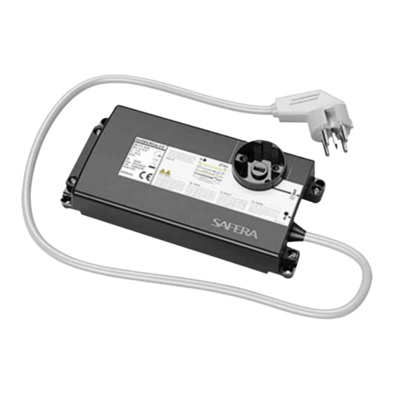
- Page 5 INSTALLATION - STEP 2/6 Mount the Power Control Unit Ⓒ. Install the Power Control Unit according to the following instructions. PCU6.3-F PCU6.1-P Fixed 3-phase connection. 1-phase, 3-pin plug OUT. See pages 10-11. See pages 16-17. PCU6.3-P PCU6.1-S Perilex-connectors. Schuko-connectors. See pages 12-13. See pages 18-19.
- Page 6 PCU6.3-F - INSTALLATION Fixed 3-phase connection. 78 mm 60 mm 225,5 mm 42 mm Optional water sensor connection. 239 mm See chapter 4. ѥ WARNING ⚐ ATTENTION Make sure that there is no power supply to Install the power control unit Ⓒ so that it 5 x 2,5 mm the cooker and the oven by removing their is not exposed to moisture.
- Page 7 PCU6.3-P - INSTALLATION 3-phase, Perilex-connectors. Mount the power cont- rol unit Ⓒ on the wall behind the cooker or into the cabinet next to the cooker. 225,5 mm L = 700 mm 51 mm + Perilex 113 mm 239 mm ѥ...
- Page 8 PCU6.1-F - INSTALLATION Fixed 1-phase connection. 78 mm 60 mm Optional water sen- sor connection. See chapter 4. 225,5 mm 42 mm 239 mm 230V MAX. 25A MICRO DISCONNECTION ѥ WARNING ⚐ ATTENTION 3 x 6 mm 3 x 6 mm Make sure that there is no power supply to Install the power control unit Ⓒ...
- Page 9 PCU6.1-P - INSTALLATION 4xA A 1-phase, 3-pin plug. 113 mm Optional water sensor 239 mm 230V MAX. 25A connection. See MICRO DISCONNECTION chapter 4. 40 mm 226 mm 95 mm 99 mm Connect the stove with 3-pin plug. ѥ WARNING ⚐...
- Page 10 PCU6.1-S - INSTALLATION 1-phase, Schuko-connectors. Mount the power control unit Ⓒ on the wall behind the cooker or into the cabinet next to the cooker. 225,5 mm L = 700 mm Optional 46,5 mm water sensor connection. See chapter 4. 230V MAX.
- Page 11 INSTALLATION - STEP 3/6 INSTALLATION - STEP 4/6 Set up the wireless connection Calibrate the system Connect the power supply Ⓓ to the Sensor unit Ⓐ: indicator light panels ❽ are lit When the indicator light panels ❽ start blinking yellow-green, you need to calibrate in purple.
- Page 12 INSTALLATION - STEP 5/6 Adjust the alarm limit Check closest When you adjust the Installation Alarm Limit Color of the indicator Number of Location of the Cooker Alarm Limit recommended alarm alarm limit, the new Height (1-12) light panels ❽ beeps limit from the refe- alarm limit is indica-...
- Page 13 INSTALLATION - STEP 6/6 Check-list 3. INSTALLATION TROUBLESHOOTING Check the working order of the appliance and fill in the installation checklist: Problem Remedy Installation is not proceeding You can re-start the installation process anytime by pres- as expected. sing the adjustment mode button ❼ for five seconds until you hear the signal and continue from step 3/6.
- Page 14 4. INSTALLING THE WATER LEAKAGE SENSOR (optional) Stove Guard can be equipped with max. four SAFERA Water Leakage Sensors. The sensors are placed in the typical leakage areas, e.g. under the dishwasher or sink. Attach the sensors Ⓕ in place.
Need help?
Do you have a question about the Siro IN-line PCU6.3-F and is the answer not in the manual?
Questions and answers