Table of Contents
Advertisement
Quick Links
Advertisement
Table of Contents

Related Manuals for Norco BIS-1280


Summary of Contents for Norco BIS-1280
- Page 1 BIS-1280 V1.0...
- Page 2 BIS-1280 V1.0 SZ HQ: 0755-27331166 Beijing Office: 010-82671166 Shanghai Office: 021-61212081 Chengdu Office: 028-85259319 Shenyang Office: 024-23960846 Xi’an Office: 029-88338386 Nanjing Office: 025-58015489 Wuhan Office: 027-87858983 Tianjin Office: 022-23727100 Singapore: 65-68530809 For more information, please visit:www.norco.com.cn...
- Page 3 Before ordering products, please learn about the product performance from the distributors to see if it is in line with your needs. NORCO is a registered trademark of Shenzhen NORCO Intelligent Technology CO., LTD. The ownership of other trademarks involved in this manual is owned by its respective owners.
- Page 4 Safety Instructions 1. Please read the product manual carefully before using this product. 2 . Put all the unused or uninstalled boards or electronic components in a static dissipative surface or static shielding bag. 3.Always ground yourself to remove any static discharge before touching the board, to place your hands on grounding metal object for a while or wear an anti-static wrist strap at all times.
-
Page 5: Table Of Contents
Content Chapter One Product Introduction ....................1 1.1 Product Introduction........................1 1.2 Hardware Specification......................1 1.3 Product Structure Dimension Drawing...................3 Chapter Two Hardware Function ....................3 2.1 Product Appearance......................... 3 2.2 External Interface Indication Diagram..................4 2.3 Front Panel I / O Connector.....................5 2.3.1 Serial Port(COM0、COM1~COM12)..............5 2.3.2 Ethernet Interface(LAN)...................6 2.3.3 USB Port.........................6... - Page 6 3.2.2 USB..........................12 3.2.3 COM..........................12 3.2.4 TF Card......................... 13 3.2.5 SATA..........................13 3.2.6 WIFI..........................13 3.2.7 3G...........................14 3.2.8 Ethernet......................... 14 3.2.9 AI.............................14 3.2.10 DI..........................15 3.2.11 DO..........................15 Appendix ..............................13 Appendix 1:Glossary........................13...
- Page 7 Packing List Thanks for purchasing NORCO products. Please check the accessories as per the packing list when you open its package. If you find any defect components or anything damaged or lost, please contact your vendor ASAP. ■ BIS-1280 ■ Power Supply Cord 2pcs ■...
- Page 8 Chapter Product Introdu ction...
-
Page 9: Chapter One Product Introduction
BIS-1280 User's Manual Chapter One Product Introduction 1.1 Introduction BIS-1280is a new generation of embedded computer room monitoring barebone product, size: 465mm×330mm×44mm; Adopt Freescale Cortex A9 architecture (single core, dual core, quad core optional) ,on board 1GB DDRIII 800MHz memory and 8GB EMMC Flash (up to 32GB)... - Page 10 BIS-1280 User's Manual ●Serial port:Provide 13xserial port,COM0 is the debugging serial port、COM1~4 support RS232/485 function、COM5~12 support RS485 function; ●USB:1x standard USB 2.0 and 1xUSB OTG; ●AI collection:Support 8x AI data collection; ●DI/DO:Support 8xDI input、4xDO output; Expansion Interface ●1xMINI PCIe card slot,on board SIM card slot,support WiFi、3G module;...
-
Page 11: Product Structure Dimension Drawing
BIS-1280 User's Manual 1.3 Product structure dimension drawing Dimension:465mm× 330mm×44mm(L×W×H)... - Page 12 Chapter Hardware Function...
-
Page 13: Chapter Two Hardware Function
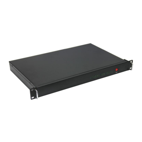
BIS-1280 User's Manual Chapter Two Hardware Function 2.1 General Appearance BIS-1280 Front view BIS-1280 Rear view... -
Page 14: External Interface Indication Diagram
BIS-1280 User's Manual 2.2 External interface indication diagram 1:BIS-1280 Front view 2:BIS-1280 Rear view... -
Page 15: Front Panel I / O Connector
2.3 Front panel I / O connector 2.3.1 Serial Port(COM0、COM1~COM12) BIS-1280 provides 13xRS232/485 serial port , 13x serial port. The location is shown in Figure 1. COM0 is the debugging serial port,Table 1 is the interface description of COM0. COM1-4 support 232/485 function,COM5-12 support RS-485 function,as shown in Figure 2, the silk... -
Page 16: Ethernet Interface(Lan
Figure 3. Figure 3 LAN1-4 Port 2.3.3 USB Port BIS-1280 provides 1x standard USB2.0 port,support hot plug, as shown in Figure 4. Figure 4 USB Port 2.3.4 VGA Port BIS-1280 provides 1xVGA display port,as shown in Figure 5. -
Page 17: Port(Ai、Di、Do
Figure 7 12V Power Interface 2.3.6 Port(AI、DI、DO) BIS-1280 provides 8xAIanalog data collection circuit、8xDI data input and 4x DO output circuit,as shown in Figure 8,Figure 9 shows the screen printing of AI、AI、DO interface,1~ 8 indicates the number of channels, SG is isolated ground signal. DO output connected to relay for isolation,D1/D2/D3/D4 are the common terminals. -
Page 18: Chassis Internal Module Circuit
BIS-1280 User's Manual 2.3.7 Ground point usage As shown in Figure 10, the grounding point of BIS-1280 casing must be connected to the ground. Figure 10 Ground Point 2.4 Chassis internal module circuit ● 1xUSB OTG; ● 1x standard 7Pin SATA port;... - Page 19 Chapter Three Software Function...
-
Page 20: Chapter Three Software Function
BIS-1280 User's Manual Chapter Three Software Function 3.1 Android System 3.1.1 VGA Instructions: use the adapter cable to turn the 2 ×5PIN box header port into VGA port, and then use the VGA cable to connect the motherboard with the monitor, and you can see the Android interface after booting. -
Page 21: Tf Card
BIS-1280 User's Manual ./android_recv /dev/ttymxc2 115200 8 0 0 2 1 485& ./android_send /dev/ttymxc1 115200 8 0 0 2 1 485 Com5、com6 mutual testing: 1.Com5 receive,com6 send: ./android_recv /dev/ttyUSB0 115200 8 0 0 2 1 485& ./android_send /dev/ttyUSB1 115200 8 0 0 2 1 485 1.Com5 receive,com6 send:... - Page 22 Connect the network cable of the test computer to BIS-1280. If the test machine can also access the network, it means that the network interface function is OK.
-
Page 23: Linux System
BIS-1280 User's Manual USB flash disk) Enter the USB flash disk directory:cd /mnt Run AI test program in USB flash disk:./DO_test 3.2 Linux System 3.2.1 VGA Instructions: use the adapter cable to turn the 2 × 5PIN box header socket interface into VGA interface, and then use the VGA cable to connect the motherboard with the monitor, and you can see the Linux interface after booting. -
Page 24: Tf Card
BIS-1280 User's Manual ./android_recv /dev/ttymxc1 115200 8 0 0 2 1 485& ./android_send /dev/ttymxc2 115200 8 0 0 2 1 485 2.Com1 receive,com2 send: ./android_recv /dev/ttymxc2 115200 8 0 0 2 1 485& ./android_send /dev/ttymxc1 115200 8 0 0 2 1 485 Com5、com6 mutual testing:... -
Page 25: Ethernet
BIS-1280 User's Manual Access to all available AP: iwlist wlan0 scanning Enable/Disable wifi:ifconfig wlan0 up/down Connect WPA/WPA2 PSK Encrypted wifi: 1. ifconfig wlan0 up 2. wpa_passphrase essid password >> /etc/wpa_supplicant.conf, for example: wpa_passphrase TP-RD norco123 >> /etc/wpa_supplicant.conf wpa_supplicant -B -c /etc/wpa_supplicant.conf -iwlan0 4. - Page 26 BIS-1280 User's Manual 3.2.10 DI Instructions:Download the DI test program to the USB flash disk, and insert the USB flash disk into the USB port when using Loading USB flash disk:mount /dev/sdX1 /mnt/ (sdX1 represents the device name of the USB flash disk) Enter the USB flash disk directory:cd /mnt...
- Page 27 Appen...
-
Page 28: Appendix
BIS-1280 User's Manual Appendix Appendix 1:Glossary ACPI Advanced Configuration and Power Management. ACPI specifications allow operating system to control most power of the computer and its add-on. Windows 98/98SE,Windows 2000 and Windows ME supports this specification. BIOS Basic input/output system. It is a kind of software including all in/out control code interface in PC. - Page 29 BIS-1280 User's Manual DIMM Dual-Inline-Memory-Modules. It is a small circuit board with memory chipset providing 64 bit memory bus width. DRAM Dynamic Random Access Memory. It’s a general type of memory for regular computer which usually store 1 bit with a transistor and a capacitance. With the development of the technology, more and more types of DRAM with different specifications exist in computer applications.
- Page 30 BIS-1280 User's Manual interface with only 6PIN; it also can connect other devices, like modem. It is the Universal Serial Bus for short. A hardware interface adapts to low speed peripherals, and is always used to connect keyboard, mouse etc. One PC can connect...
Need help?
Do you have a question about the BIS-1280 and is the answer not in the manual?
Questions and answers