
Summary of Contents for Hansford sensors HS-517
- Page 1 Vibration Monitoring For Industrial Applications User Manual HS-517 Vibration Trip Display www.hansfordsensors.com © 2021 Hansford Sensors...
- Page 2 HS-517 User Manual HS-XXX User Manual HS-517 Vibration Trip Display User Manual Hansford Sensors Ltd. This document may not be reproduced in any way without the prior written permission of the company. QM039 Issue 1...
-
Page 3: Table Of Contents
HS-517 User Manual Contents 1. General and Safety-Related Information 1.1 Symbols Used 1.2 Staff Qualification 1.3 Intended use 1.4 Foreseeable misuse 1.5 Limitation of liability and warranty 1.6 Safe handling 1.7 Safety-related maximum values 1.8 Scope of delivery 2. Product Identification 3. -
Page 4: General And Safety-Related Information
HS-517 User Manual 1. General and Safety-Related Information on this Operating Manual This operating manual enables safe and proper handling of the product, and forms part of the device. It should be kept in close proximity to the place of use, accessible for staff members at any time. -
Page 5: Symbols Used
HS-517 User Manual 1.1 Symbols Used Type and source of danger Measures to avoid the danger. Warning word Warning word Meaning Imminent danger! Non-compliance will result in death or serious injury. DANGER Possible danger! Non-compliance may result in death or serious injury. -
Page 6: Intended Use
Vibration Transmitters HS-420I and HS-422I Series with 4...20mA 2-wire analogue output. The HS-517 may be used with all transmitters if the following requirements are met: • output signal of the transmitter: 4 … 20 mA / 2-wire • suitable electrical connection (according to data sheet) -
Page 7: Foreseeable Misuse
The digital plug-on display HS-517 must not be used particularly in the following cases: In areas for which the device has no approval. When the HS-517 is used in combination with other devices, the approval of the device with the lowest approved area applies. -
Page 8: Product Identification
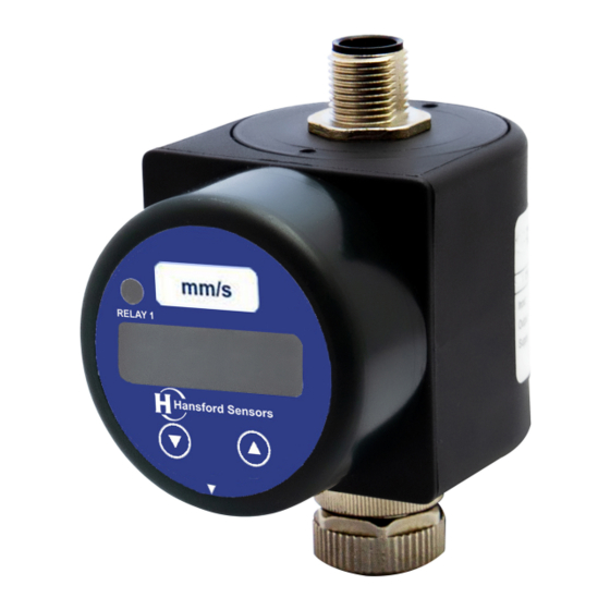
HS-517 User Manual 2. Product identification The device can be identified by means of the manufacturing label with order code. The most important data can be gathered therefrom. The version of the firmware, (e. g. P07) will appear for about 1 second in the display after starting up the device. -
Page 9: Mounting
HS-517 User Manual 3. Mounting 3.1 Mounting and safety instructions Danger of death from explosion, airborne parts, leaking fluid, electric shock Always mount the device in a depressurized and de-energized condition! DANGER Do not install the device while there is a risk of explosion. -
Page 10: Mounting Steps For M12X1 Connectors
3.2 Mounting steps for M12x1 connectors Plug the vibration trip display onto the transmitter. Plug the cable socket or mating plug onto the HS-517 and fasten it properly. 3.3 Positioning of the display module In order to ensure easy readability even when the device is installed in an awkward location, the display can be rotated into the desired position. -
Page 11: Electrical Connection
HS-517 User Manual 4. Electrical connection 4.1 Connection and safety instructions Danger of death from electric shock or explosion - Explosion hazard if the operating voltage is too high (max. 28 V - Always mount the device in a depressurized and... -
Page 12: Conditions For The Explosion-Hazardous Area
HS-517 User Manual 4.2 Conditions for the explosion-hazardous area Danger generated by electrostatic charging Danger of death from explosion Explosion hazard due to spark formation from electrostatic charging of plastic components. If devices are equipped with a cable outlet, the connection cable routing must be fixed. - Page 13 HS-517 User Manual NOTE - Observe item (17) of the type-examination certificate which specifies special conditions for intrinsically safe operation. Exemplary circuit description The supply voltage of e. g. 24 V provided by the power supply is led across the Zener barrier.
- Page 14 HS-517 User Manual Calculation example for the selection of the Zener barrier The nominal voltage of the power supply in front of the Zener barrier is 24 VDC ± 2%. This results in: - greatest supply voltage: V = 24 V * 1.02 = 24.48 V...
-
Page 15: Electrical Installation
HS-517 User Manual 4.3 Electrical installation Connect the device electrically according to the information specified on the type plate, the following table, and the connection circuit diagram. Pin configuration: M12x1, metal Electrical (5-pin) connections Supply + Supply − Relay 1... -
Page 16: Commissioning
3. Enter the Serial number, sign the calibrated by and date the date of HS-517 User Manual 4. Cut out the certificate of calibration and include this with the items. 5. Commissioning Danger of death from explosion Explosion hazard if the operating voltage is too high (max. -
Page 17: Configuration
HS-517 User Manual Button functions • move forward in the menu system (beginning with menu 1) • increase the displayed value note: increase the counting speed by keeping the button pushed for more than 5 second • move backwards in the menu system (beginning with the last menu) •... -
Page 18: Password System
HS-517 User Manual 6.3 Password system The device can be locked in order to prevent configuration by unauthorized persons. Refer to menu 1 of the menu list for more information. 6.4 Unit The unit of the measured value is already determined at the time of ordering by the desired measuring range. -
Page 19: Menu System Structure
HS-517 User Manual 6.6 Menu system structure Display mode (measured value is displayed) PA on - Password active Access protection/ Special menu 1: entry to special Full scale set menus FS S Menu 1: Code-No.: 0238 PAon / PAof PA of -... -
Page 20: Menu List
HS-517 User Manual 6.7 Menu list button functions are well known (see ″7.1 Control and display elements″) menu 1 – access protection password active PAon to deactivate: set password password inactive PAof to activate: set password ... - Page 21 HS-517 User Manual special menus (to access a special menu, select the menu item "PAof" with the ▲- or ▼-button and confirm it; "1" appears in the display) special menu 1 – full scale compensation for full scale compensation, which is necessary if the...
-
Page 22: Maintenance
HS-517 User Manual 7. Maintenance Danger of death from explosion, airborne parts, leaking fluids, electric shock Working on supplied (active) parts, except for intrinsically safe circuits, is principally prohibited during an explosion hazard! DANGER Always service the device in a depressurized... -
Page 23: Service/Repair
HS-517 User Manual 9. Service / repair Information on service / repair: www.hansfordsensors.com sales@hansfordsensors.com Danger of injury from aggressive media or pollutants - Depending on the measured medium, this may constitute a danger to the operator. - Wear suitable protective clothing WARNING e.g. -
Page 24: Warranty Terms
HS-517 User Manual 11. Warranty terms The warranty terms are subject to the legal warranty period of 24 months, valid from the date of delivery. If the device is used improperly, modified or damaged, we will rule out any warranty claim. A damaged diaphragm will not be accepted as a warranty case. -
Page 25: Eu Declaration Of Conformity
EU DECLARATION OF CONFORMITY INSTRINSICALLY SAFE PRODUCTS ATEX DIRECTIVE 2014/34/EU We Hansford Sensors of Artisan, Hillbottom Road, Sands Industrial Estate, High Wycombe HP12 4HJ, UK Declare under our sole responsibility that the Type HS-517I Accelerometers/Accelerometer Systems comply with the above directive and 1.*Meet the requirements of 2014/30/EU (EMC) EN 61326-1:2013... - Page 26 Hansford Sensors Ltd. Artisan, Hillbottom Road, Sands Industrial Estate, High Wycombe, Buckinghamshire, HP12 4HJ, England. Tel: +44 (0)845 680 1957 Web: www.hansfordsensors.com - 25 - QM039 Issue 1...
- Page 27 sales@hansfordsensors.com +44 (0) 845 680 1957...
Need help?
Do you have a question about the HS-517 and is the answer not in the manual?
Questions and answers