
Related Manuals for Arbor Technology IEC-3350


Summary of Contents for Arbor Technology IEC-3350
- Page 1 IEC-3350 Fanless Boxed Chassis System with Intel® Celeron® Processor User’s Manual Version 1.0 2020.09 P/N: 4010335000100P...
- Page 2 This page is intentionally left blank. - 2 -...
- Page 3 Revision History Version Date Description 2020.09 Initial release - i -...
-
Page 4: Table Of Contents
Contents Revision History ................i Preface................... iv Copyright Notice ..................iv Declaration of Conformity .................iv CE ......................iv FCC Class A ..................iv RoHS ....................v SVHC / REACH ................. v Important Safety Instructions ..............vi Warning ....................vii Replacing Lithium Battery ................vii Technical Support ..................vii Warranty ....................viii Chapter 1 - Introduction .............. - Page 5 Contents Chapter 5 - BIOS ................33 5.1. Entering Setup ................. 34 5.1.1. Function Keys ................ 35 5.1.2. Menu Bars ................35 5.2. Main Menu ..................36 5.3. Advanced Menu ................37 5.4. Chipset Menu .................. 48 5.5. Security Menu .................. 50 5.6.
-
Page 6: Preface
Preface Preface Copyright Notice All Rights Reserved. The information in this document is subject to change without prior notice in order to improve the reliability, design and function. It does not represent a commitment on the part of the manufacturer. Under no circumstances will the manufacturer be liable for any direct, indirect, special, incidental, or consequential damages arising from the use or inability to use the product or documentation, even if advised of the possibility of such... -
Page 7: Rohs
(PBDE) in electrical and electronic products. Member states of the EU are to enforce by 7/1/2006. ARBOR Technology Corp. hereby states that the listed products do not contain unintentional additions of lead, mercury, hex chrome, PBB or PBDB that exceed a maximum concentration value of 0.1% by weight or for cadmium exceed... -
Page 8: Important Safety Instructions
Preface Important Safety Instructions Read these safety instructions carefully Read all cautions and warnings on the equipment. Place this equipment on a reliable surface when installing. Dropping it or letting it fall may cause damage Make sure the correct voltage is connected to the equipment. For pluggable equipment, the socket outlet should be near the equipment and should be easily accessible. -
Page 9: Warning
Preface Warning The Box PC and its components contain very delicately Integrated Circuits (IC). To protect the Box PC and its components against damage caused by static electricity, you should always follow the precautions below when handling it: Disconnect your Box PC from the power source when you want to work on the inside. -
Page 10: Warranty
Preface Warranty This product is warranted to be in good working order for a period of one year from the date of purchase. Should this product fail to be in good working order at any time during this period, we will, at our option, replace or repair it at no additional charge except as set forth in the following terms. -
Page 11: Chapter 1 - Introduction
Chapter 1 Introduction Chapter 1 - Introduction - 1 -... -
Page 12: Product Highlights
Introduction 1.1. Product Highlights • Ultra Low Power and Fanless Design • HDMI / DisplayPort output supported • Optional Wi-Fi Connection supported • Rugged Design for Shock/Vibration Protection • Easy Installation/Maintenance 1.2. About this Manual This manual is meant for the experienced users and integrators with hardware knowledge of personal computers. - Page 13 Introduction Video Port 2 x DisplayPort Audio 1 x Headpone jack connector for Line-out & Mic Expansion Bus 1 x Mini-card socket (Full Size) Environmental Operating Temp. 0 ~ 50°C (32 ~ 122°F), ambient w/ air flow Storage Temp. -40 ~ 85°C (-40 ~ 185°F) Operating Humidity 10 ~ 95% @ 60°C (non-condensing) Vibration...
-
Page 14: Inside The Package
Upon opening the package, carefully inspect the contents. If any of the items is missing or appears damaged, contact your local dealer or distributor. The package should contain the following items: 1 x IEC-3350 1 x Accessory Box that contains the following items: •... -
Page 15: Standard Accessories
Introduction 1.5.1. Standard Accessories 12VDC, 5A, 60W, 2.5φ JACK, AC/DC Power Adaptor Adaptor with power cord WMK-3350 Wall mount kit COM Port Cable RJ-45 to DB-9 male cable 1.5.2. Configure-to-Order Service Make the computer more tailored to your needs by selecting one or more components from the list below to be fabricated to the computer. - Page 16 This page is intentionally left blank. - 6 -...
-
Page 17: Chapter 2 - Getting Started
Chapter 2 Getting Started Chapter 2 - Getting Started - 7 -... -
Page 18: Dimensions
Getting Started 2.1. Dimensions Unit:mm - 8 -... -
Page 19: Take A Tour
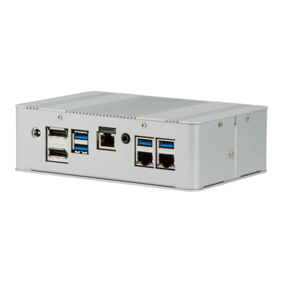
Getting Started 2.2. Take A Tour Front View Antenna Hole Power Button RS-232 RS-232 Serial Port Serial Port Rear View Micro SD Card Socket DP Ports USB 3.0 Ports RJ-45 LAN USB 3.0 Ports Line out 12V DC-In & Mic Ports Power Jack COM Port... -
Page 20: Driver Installation Notes
Getting Started 2.3. Driver Installation Notes The computer supports Windows 10. To install the drivers, please go to our website at www.arbor-technology.com and download the driver pack from the product page. Device Driver Path Audio \Audio Chipset \Chipset\inf Ethernet \Ethernet\intellan IRMT \IRMT \ISH... -
Page 21: Chapter 3 - System Configuration
Chapter 3 System Configuration Chapter 3 - System Configuration - 11 -... -
Page 22: Board Layout
System Configuration 3.1. Board Layout PWOUT (1)EDP (5) COM2, COM3 SATA (4)USB2 (5)COM6 (5)COM5 (5)COM4 (6)GPIO (7)FP_AUDIO (3)SPDIFOUT CPUFAN (9)FP AT_MODE (9)SMBUS (8)PS2KBMS (10)I2C JBAT DCIN3 - 12 -... - Page 23 System Configuration Micro-SD Card Socket Intel CPU - 13 -...
-
Page 24: Jumpers
System Configuration 3.2. Jumpers ➊ JP1 (4-pin): COM1 Port Pin9 Function Select COM1 Port Pin-9 → 2-4 Closed: 3-4 Closed: 4-6 Closed: RI=NC; RI= 5V; RI= 12V. ➋ JP2 (3-pin): MPE Slot Power Select JP2 → MPE Slot Power 1-2 Close: 3.3V Selected(Default); 2-3 Close: 3.3VSB Selected. - Page 25 System Configuration ➍ JP4 (4-pin): eDP Inverter Power Select JP4→eDP Inverter VCC 2 4 6 2 4 6 1 3 5 1 3 5 1 3 5 2-4 Closed: eDP 4-6 Closed: eDP 3-4 Closed: eDP Inverter VCC= 5V Inverter VCC= Inverter VCC= 12V;...
- Page 26 System Configuration ➐ AT_MODE (3-pin): AT/ATX Mode Function Select 1-2 Closed: ATX Mode Selected; 2-3 Closed: AT Mode Selected. ➑ JBAT (2-pin): CMOS Clear Setting JBAT→ CMOS Clear Setting 1-2 Open: Normal; 1-2 Closed:Clear CMOS. - 16 -...
-
Page 27: Connectors
System Configuration 3.3. Connectors ① Rear Panel Connectors RJ-45 LAN Ports USB 3.0 Ports Line out (RJ-45 Type) & MIC 12V DC-in Power Jack DP Ports USB 3.0 Ports Micro SD Card Socket Connector Description This connector is standard RJ-45 LAN jack for Network RJ-45 LAN Port connection. - Page 28 System Configuration ③ PWROUT (4-pin): SATA Power Connector ④ SATA (7-pin Block): SATAIII Port connector Pin No. Definition ⑤ CPUFAN (4-pin): CPU FAN Connector - 18 -...
-
Page 29: Headers
System Configuration 3.4. Headers (1)EDP (40-pin): eDP Header Pin21 Pin40 Pin20 Pin1 Pin NO. Pin Define Pin NO. Pin Define Pin 1 Pin 21 Pin 2 Pin 22 Pin 3 Lane3_N Pin 23 Pin 4 Lane3_P Pin 24 Pin 5 Pin 25 Pin 6 Lane2_N... - Page 30 System Configuration (3)SPDIFOUT (2-pin): HDMI SPDIF Out Header Pin1 (4)USB2 (9-pin): USB 2.0 Port Pin Header Pin 1 (5)COM2/3/4/5/6 (9-pin): Serial Port Headers - 20 -...
- Page 31 System Configuration Pin NO. RS232 *RS422 *RS485 Pin 1 DATA- Pin 2 DATA+ Pin 3 Pin 4 Pin 5 Pin 6 Pin 7 Pin 8 Pin 9 Pin6 Pin1 Pin5 (6)GPIO (10-pin): GPIO Header Pin 1 (7)FP (8-pin): Front Panel Header Pin 1 MIC2-L MIC2-R...
- Page 32 System Configuration (8)PS2KBMS (6-pin): PS/2 Keyboard & Mouse Header MS_CLK MS_DATA KB_DATA Pin 1 KB_CLK (9)SMBUS (5-pin): SMBUS Header 3VSB SMBUS_ALERT SMBUS_DATA SMBUS_CLK Pin 1 (10)I2C(4-pin): I2C Header I2C_DATA I2C_CLK 3.3V Pin 1 - 22 -...
-
Page 33: Chapter 4 - Installation And Maintenance
Chapter 4 Installation and Maintenance Chapter 4 - Installation and Maintenance - 23 -... -
Page 34: Disassemble The Computer
Installation & Maintenance 4.1. Disassemble the Computer Place the computer upside down on a flat surface. Loosen and remove the 6 screws from the computer's bottom side. Remove the bottom cover completely from the computer. M.2 socket Mini-card socket for Wi-Fi module for SSD SIM socket for... -
Page 35: Install Memory Module
Installation & Maintenance 4.2. Install Memory Module The main board has one dual inline memory module (DIMM) socket. Load the computer with a memory module to make the computer run programs. The memory module for the computer’s SO-DIMM socket should be a 204-pin DDR3L with a “key notch”... -
Page 36: Install M.2 Module
Installation & Maintenance Press down the memory module until it is auto-locked in place. 4.3. Install M.2 Module Plug the M.2 module to the socket’s connector by a slanted angle. Fully plug the module, and note the notch on the module should meet the break of the connector. - Page 37 Installation & Maintenance Insert the SIM card into the card holder as shown below. Close the SIM card holder door and slide the door to the LOCK edge to lock into place. - 27 -...
-
Page 38: Install Wi-Fi Module
Installation & Maintenance 4.5. Install Wi-Fi Module Prepare the Wi-Fi module kit. The module is a half-size module of PCI Express Mini-card form factor, with two U.FL connectors, one is “MAIN“ (marked 0), and the other is “AUX“ (marked 1). Two U.FL connectors, one is “MAIN”... - Page 39 Connect the RF antenna’s MHF connector to the Wi-Fi module’s main connector (marked 0) Extend the half-size module with a “mini half bracket”. Join them together by using two screws as shown below. Plug the Wi-Fi module to the socket’s connector by a slanted angle. Fully plug the module, and note the notch on the wireless module should meet the break of the connector.
- Page 40 Press the module down and fix the module in place using one screw. Remove the plastic plug from the computer's rear panel to make antenna hole. Keep the plastic plug for any possible restoration in the future. From the other end of the RF antenna, which is an SMA connector, remove the washer and the nut.
- Page 41 Flat side of the connector Arrange the flat side of the SMA connector to meet the flat side of the antenna hole. 10. Mount the washer first and then the nut to the SMA connector. Make sure the nut is tightened. Mount the washer and the nut to the SMA connector.
-
Page 42: Wall Mounting (Optional)
4.6. Wall Mounting (optional) Prepare the wall mount kit and a screwdriver for wall mounting. Follow the instructions below: Position the computer with the bottom side facing up. Align the screw holes of the wall mount bracket with the ones of the main unit. -
Page 43: Chapter 5 - Bios
Chapter 5 BIOS Chapter 5 - BIOS - 33 -... -
Page 44: Entering Setup
BIOS The BIOS is a program located on a Flash Memory on the motherboard. This program is a bridge between motherboard and operating system. When you start the computer, the BIOS program will gain control. The BIOS first operates an auto-diagnostic test called POST (power on self test) for all the necessary hardware, it detects the entire hardware device and configures the parameters of the hardware synchronization. -
Page 45: Function Keys
BIOS 5.1.1. Function Keys In the above BIOS Setup main menu of, you can see several options. We will explain these options step by step in the following pages of this chapter, but let us first see a short description of the function keys you may use here: Press←... -
Page 46: Main Menu
BIOS 5.2. Main Menu Main menu screen includes some basic system information. Highlight the item and then use the <+> or <-> and numerical keyboard keys to select the value you want in each item. System Date Set the date. Please use [Tab] to switch between date elements. System Time Set the time. -
Page 47: Advanced Menu
BIOS 5.3. Advanced Menu OS Selection The optional settings: [Windows]; [Intel Linux]; [MSDOS]. * Note: User need to go to this item to select the OS mode before installing corresponding OS driver, otherwise problems will occur when installing the driver. ►... - Page 48 BIOS Use this item to select the highest ACPI sleep state the system will enter when the suspend button is pressed. The optional settings are: [Suspend Disabled]; [S3 (Suspend to RAM)]. ► Wake-up Function Settings Press [Enter] to make settings for the following sub-item: Wake-up System With Fixed Time The optional setting are: [Enabled];...
- Page 49 BIOS Serial Port Use this item to [Enabled] or [Disabled] serial port (COM). Change Settings Use this item to select an optimal setting for super IO device. Serial Port FIFO Mode The optional settings are: [16-Byte FIFO]; [32-Byte FIFO]; [64-Byte FIFO];...
- Page 50 BIOS WatchDog Wake-up Timer in ERP This item support WDT wake-up while ERP function is set as [Enabled]. The optional settings are: [Enabled]; [Disabled]. When set as [Enabled], the following sub-items shall appear: WatchDog Timer Value in ERP User can select a value in the range of [10] to [4095] seconds when ‘WatchDog Timer Unit in ERP’...
- Page 51 BIOS SmartFAN Configuration CPUFAN Type The optional settings are: [3-Pin]; [4-Pin]. CPUFAN Smart Mode The optional settings are: [Disabled]; [Enabled]. When set as [Enabled], the following sub-items shall appear: CPUFAN Full-Speed Temperature Use this item to set CPUFAN (/SYSFAN1/SYSFAN2) full speed temperature.
- Page 52 BIOS When set as [Enabled], user can make further settings in the ‘Console Redirection Settings’ screen: ► Console Redirection Settings The settings specify how the host computer and the remote computer (which the user is using) will exchange data. Both computers should have the same or compatible settings.
- Page 53 BIOS Putty Keypad The optional settings are: [VT100]; [LINUX]; [XTERMR6]; [SCO]; [ESCN]; [VT400]. Redirection After BIOS POST The optional settings are: [Always Enable]; [BootLoader]. Legacy Console Redirection ► Legacy Console Redirection Settings Press [Enter] to make settings in ‘Legacy Serial Redirection Port’. Legacy Serial Redirection Port Use this item to select a COM port to display redirection of Legacy OS and Legacy OPROM messages.
- Page 54 BIOS Bits per second The optional settings are: [9600]; [19200]; [57600]; [115200]. Flow Control The optional settings are: [None]; [Hardware RTS/CTS]; [Software Xon/ Xoff]. Data Bits The default setting is: [8]. *This item may or may not show up, depending on different configuration. Parity The default setting is: [None].
- Page 55 BIOS When set as [Enabled], the following item shall appear: Enhanced C state Use this item to enable or disable CPU Enhanced C state. The optional settings: [Disabled]; [Enabled]. Max Core C-State This item controls Max C-state that the processor will support. The optional settings: [Fused value];...
- Page 56 BIOS Ipv6 HTTP Support The optional settings are: [Disabled]; [Enabled]. Use this item to enable Ipv6 HTTP Boot Support. When set as [Disabled], Ipv6 HTTP boot optional will not be created. PXE boot wait time Use this item to set wait time to press [ESC] key to abort the PXE boot. Media detect count Use this item to set the number of times which media will be checked.
- Page 57 BIOS ► USB Configuration Press [Enter] to make settings for the following sub-items: USB Configuration Legacy USB Support The optional settings are: [Enabled]; [Disabled]; [Auto]. [Enabled]: To enable legacy USB support. [Disabled]: To keep USB devices available only for EFI specification, [Auto]: To disable legacy support if no USB devices are connected.
-
Page 58: Chipset Menu
BIOS Select [Manual] you can set value for the following sub-item: ‘Device Power-up Delay in Seconds’. Device Power-up Delay in Seconds The delay range is from [1] to [40] seconds, in one second increments. ► Intel I211 Gigabit Network Connection (MAC:XX:XX:XX:XX:XX:XX) Use this item to get MAC address information. - Page 59 BIOS The optional settings: [128MB]; [256MB]; [MAX]. PAVP Enable The optional settings: [Enabled]; [Disabled]. Brightness Level The optional settings: [20]; [40]; [60]……. [240]; [255]. South Cluster Configuration Press [Enter] to make settings for the following sub-items: ► SATA Configuration SATA Controller The optional settings: [Enabled];...
-
Page 60: Security Menu
BIOS The optional settings: [Enabled]; [Disabled] Onboard Lan2 Controller The optional settings: [Enabled]; [Disabled] System State After Power Failure The optional settings: [Always Off]; [Always On]; [Former state] 5.5. Security Menu Security menu allow users to change administrator password and user password settings. - Page 61 BIOS ► Key Management Press [Enter] to make settings for the following items: Provision Factory Defakt Keys The optional settings: [Disabled]; [Enabled]. Enroll all Factory Default Keys The optional settings: [Yes]; [No]. Press [Yes] to install default keys. Save all Secure Boot Variables Press [Enter] to save secure boot variables.
-
Page 62: Boot Menu
BIOS 5.6. Boot Menu Setup Prompt Timeout Use this item to set number of seconds to wait for setup activation key. Bootup Numlock State Use this item to select keyboard numlock state. The optional settings are: [On]; [Off]. Quiet Boot The optional settings are: [Disabled];... -
Page 63: Save & Exit Menu
BIOS 5.7. Save & Exit Menu Save Changes and Reset This item allows user to reset the system after saving the changes. Discard Changes and Reset This item allows user to reset the system without saving any changes. Restore Defaults Use this item to restore /load default values for all the setup options. - Page 64 BIOS Launch EFI Shell from filesystem device This item is used for attempts to launch EFI shell application from one of the available file system devices. - 54 -...
Need help?
Do you have a question about the IEC-3350 and is the answer not in the manual?
Questions and answers